
Related Manuals for Kongsberg Robertson RI9


Summary of Contents for Kongsberg Robertson RI9
- Page 1 INSTRUCTION MANUAL Robertson RI9 Rudder Angle Indicator Stand alone systems and connections to Autopilot systems 20220562...
- Page 2 NOTE! Simrad Robertson AS makes every effort to ensure that the information contained within this document is correct. However, our equipment is continuously being improved and updated, so we cannot assume liability for any errors which may occur. The information contained within this document remains the sole property of Simrad Robertson AS.
- Page 3 Instruction manual Instruction Manual This manual is intended as a reference guide for operating and correctly installing the RI9 Rudder Angle Indicator. Please take time to read the manual to get a thorough understanding of the indicator system and its relationship to a complete autopilot system.
-
Page 4: Table Of Contents
Robertson RI9 Rudder Angle Indicator Contents RI9 RUDDER ANGLE INDICATOR .............. 3 General......................3 Technical specifications................3 Installation....................4 Stand alone rudder angle indicator(s) ............. 5 Connection to autopilot junction units ............ 5 RI9 set-up ..................... 7 Maintenance....................10 RI9 spare parts................... 10 RF14XU RUDDER FEEDBACK UNIT ............ -
Page 5: Ri9 Rudder Angle Indicator
Instruction manual RI9 RUDDER ANGLE INDICATOR General The RI9 is manufactured in non-corrosive aluminum with a non- reflective black finish. It is designed to operate from both voltage and current signals. The RI9 can also operate from the earlier Robertson "Standard" rudder feedback units. -
Page 6: Installation
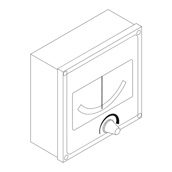
Robertson RI9 Rudder Angle Indicator 144 (5.67") 57 (2.24") Panel cut-out:138x138 (5.44") 65 (2.56") Fig. 1-1. RI9 Dimensions Installation The RI9 is designed for bulkhead or panel mounting, and should be positioned in a location in clear view of the helmsman and the ship's officers. -
Page 7: Stand Alone Rudder Angle Indicator(S)
Instruction manual Fig. 1-3. RI9 Bulkhead mounting Stand alone rudder angle indicator(s) The RI9 indicator can be used in stand alone rudder angle indicator systems as described in sections 2 and 3 of this manual or as part of an autopilot system as described below. Connection to autopilot junction units All interconnection cables should be screened, 1.5 mm (AWG14) - Page 8 Robertson RI9 Rudder Angle Indicator Fig. 1-5. RI9-J200S Wiring diagram Fig. 1-6. RI9-J101A Wiring diagram Fig. 1-7. RI9-J45A Wiring diagram 20220562C...
-
Page 9: Ri9 Set-Up
Instruction manual RI9 set-up The RI9 indicator is calibrated for voltage input signal (RF14XU Rudder Feedback Unit). Assuming that the mechanical linkage is in accordance with the instruction on Fig. 2-2 adjustment of the trimpotmeters marked Voltage FB, G (=Gain) and O (= Offset) is not necessary. - Page 10 Robertson RI9 Rudder Angle Indicator When changing from voltage to current signal (or vice versa), Note ! the indicator may have to be recalibrated. In this case, or if the Gain and Offset trimpot’s for other reasons are maladjusted, the following calibration procedure should be carried out: 1.
- Page 11 Instruction manual Fig. 1-9. RI9 Schematic diagram (N3-201562-) 20220562C...
-
Page 12: Maintenance
Robertson RI9 Rudder Angle Indicator Maintenance Robertson rudder indicator equipment will need no special attention besides replacing illumination bulbs (See Fig. 1-10 for location of bulbs). It is, however, essential that the mechanical linkage between the rudder stock and the shaft of the rudder feedback unit is regularly checked and maintained in good condition to avoid misalignment. -
Page 13: Rf14Xu Rudder Feedback Unit
Instruction manual RF14XU RUDDER FEEDBACK UNIT General The rudder feedback unit transmits a signal proportional to the rudder angle. It is mounted close to the rudder stock and is mechanically connected to the rudder by a transmission link in a 1:1 ratio. The RF14XU Rudder Feedback Unit consists of a glass- reinforced non-flammable polyester housing with a mounting plate of sea-water resistant aluminium. -
Page 14: Technical Specifications
Robertson RI9 Rudder Angle Indicator Technical specifications Dimensions: ....See Fig. 2-1 Protection: ..... IP56 Ambient temperature:.. –25 - +55°C Operating voltage:..19-40V Frequency section 12-40V DC Output RAI: ....Midship reference 0.5 x supply voltage Full deflection ±9V Output autopilot: 3400Hz ±20Hz/degree... -
Page 15: Installation
Instruction manual Installation Before installation check that the alignment mark on the mounting plate agrees with the mark on the shaft. Bring the rudder to midships position. The feedback unit should be mounted on a plane surface and secured by bolts through the three holes in the mounting plate. - Page 16 Robertson RI9 Rudder Angle Indicator run in a conduit between the rudder feedback unit and the rudder indicator(s). The cable screen must be connected to the internal ground terminal. Ref. picture below. Fig. 2-3 Screen termination The feedback unit has an external ground terminal and must have a proper ground connection to the hull.
- Page 17 Instruction manual Fig. 2-5. RI9-RF14XI Wiring diagram VOLTAGE FB SUPPLY - SUPPLY + VOLTAGE FB SUPPLY - SUPPLY + VOLTAGE FB SUPPLY - SUPPLY + Fig. 2-6. Wiring diagram RI9, Panorama and RF14XU on 24V DC Mains 20220562C...
- Page 18 Robertson RI9 Rudder Angle Indicator VOLTAGE FB SUPPLY - SUPPLY + VOLTAGE FB SUPPLY - SUPPLY + VOLTAGE FB SUPPLY - SUPPLY + Fig. 2-7. Wiring diagram Panorama and RI9 on AC Mains using a Robertson RI4 Rectifier and “standard rudder potentiometer”...
- Page 19 Instruction manual VOLTAGE FB SUPPLY - SUPPLY + VOLTAGE FB SUPPLY - SUPPLY + VOLTAGE FB SUPPLY - SUPPLY + Fig. 2-8 Wiring diagram Panorama and RI9 on AC Mains with regulated power supply 20220562C...
- Page 20 Robertson RI9 Rudder Angle Indicator VOLTAGE FB SUPPLY - SUPPLY + VOLTAGE FB SUPPLY - SUPPLY + VOLTAGE FB SUPPLY - SUPPLY + Fig. 2-9 Wiring diagram RI9, Panorama Mk2 and RF14XU on 24V DC Mains 20220562C...
- Page 21 Instruction manual VOLTAGE FB SUPPLY - SUPPLY + VOLTAGE FB SUPPLY - SUPPLY + VOLTAGE FB SUPPLY - SUPPLY + Fig. 2-10 Wiring diagram Panorama Mk2 and RI9 on AC Mains using a Robertson RI4 Rectifier and “Standard Rudder Potentiometer” 20220562C...
- Page 22 Robertson RI9 Rudder Angle Indicator VOLTAGE FB SUPPLY - SUPPLY + VOLTAGE FB SUPPLY - SUPPLY + VOLTAGE FB SUPPLY - SUPPLY + Fig. 2-11 Wiring diagram Panorama Mk2 and RI9 on AC Mains with regulated power supply 110/220VAC – 24VDC 2A...
-
Page 23: Other Rudder Angles
Instruction manual Other rudder angles The RF14XU is normally delivered for ±45 degrees rudder angle (violet, brown and pink leads are not connected). For ±60 degrees, connect brown lead to terminal 10. For ±70 degrees, connect pink to terminal 10 and for ±90 degrees, connect the violet lead to terminal 10. -
Page 24: Adjustments
Robertson RI9 Rudder Angle Indicator VIOLET RF14XU ELECTRONIC MODULE BROWN (VIEWED FROM BACK SIDE) PINK NOTE 2 BLUE (GND) POT. YELLOW (+5V) METER GREEN (WIPER) NOTE 1 NOTE 1: Brown lead normally connected to Move to to invert the rudder indicator deflection. -
Page 25: Spare Parts
Instruction manual Spare parts Part no. Pos. Description 22504005 Transmission Link 44132306 Ball joint 22500300 Shaft coupling 22500458 Gasket 22501605 Electronic XU drive module 44105120 Actuator 44105146 Limit switch 44118388 Potentiometer 5Kohm 44132033 Corrosion inhibitor sponge 22500284 Activator block 22500276 Activator disc Fig. -
Page 26: Rf45 And Rf45X Rudder Feedback Units
Robertson RI9 Rudder Angle Indicator RF45 AND RF45X RUDDER FEEDBACK UNITS General The RF45/RF45X transmits two electrical signals proportional to the rudder angle. A frequency signal is feedback for the autopilot. The other, a current signal, is for rudder angle indicators. -
Page 27: Technical Specifications
Instruction manual Technical specifications Dimensions: ......See Fig. 3-1 Protection: ......IP56 Ambient temperature:..–10 - +55°C Operating voltage:..... 12V DC (RF45X: 12/24V DC) Frequency output: ..... 3400 Hz (midship reference) Port: +20Hz/degree, starboard: –20Hz/degree Current output (RAI): ..0,1-1,1 mA (0,6 mA midships) Capacity: ...... -
Page 28: Rf45X
Robertson RI9 Rudder Angle Indicator Shaft pointing up: Strap S1 - S3 and S2 - S4. Shaft pointing down: Strap S1 - S2 and S3 - S4. RF45X The S2 plug-in straps have to be “turned” 90° to achieve reversed output signal. - Page 29 Instruction manual Fig. 3-4 RF45 Template (N4-201122 Scale 1:1 20220562C...
- Page 30 Robertson RI9 Rudder Angle Indicator 20220562C...
-
Page 31: Electrical Connection
Instruction manual Fig. 3-5 RF45 - Mounting Electrical connection Fig. 3-6. RI9-RF45 Wiring diagram For RF45X the supply voltage can be 12/24VDC. Note ! 20220562C... -
Page 32: Spare Parts
Robertson RI9 Rudder Angle Indicator Spare parts RF45 Rudder Feedback Unit 22011050 RF45 Rudder Feedback Unit w/transmission link 22011068 RF45 Rudder Feedback Unit 22011183 T45 Transmission link, complete 44151744 Screw M5x16 A2 22011100 RF45 Lid RF45 housing with s.n. 5940K20 onwards will need lid with rev. -
Page 33: Rf45X Rudder Feedback Unit
Instruction manual RF45X Rudder Feedback Unit 22011282 RF45X Rudder Feedback Unit w/ transmission link 22011290 RF45X Rudder Feedback Unit 22011183 RF45 Transmission Link 44156644 Transmission rod M8x50 44157097 Ball joint socket 22504039 Transmission lever 22011217 Mounting kit 22011266 RF45X Board Ass’y with potentiometer 20220562C... - Page 34 Robertson RI9 Rudder Angle Indicator 20220562C...
- Page 35 Tel.: +358 9 5494 2600 Fax: +972 4 8627404 (Alicante) Fax: +358 9 5494 2700 ITALY Tel.: +34 96 681 0149 SAUDI ARABIA Kongsberg Simrad Srl. Fax: +34 96 685 2304 (MarineLine) SAMACO Via Carlo Veneziani, 58 Maritim Oy Saudi Arab Marketing 00148 Rome Veneentekijäntie 1...
- Page 36 Robertson RI9 Rudder Angle Indicator UNITED ARAB Jason Electronics Pte Ltd. JAPAN CHILE EMIRATES Blk 194 Pandan Loop Shipmate Japan Co. Ltd. Simrad S.A. Maritronics #06-05 Ohsanbashi Bldg., 3 Providencia 1100 P.O. Box 6488 Pantech Industrial 1-1 Kaigan-Dori Naka- Torre C.Dpto. 404...
Need help?
Do you have a question about the Robertson RI9 and is the answer not in the manual?
Questions and answers