Table of Contents
Advertisement
Available languages
Available languages
Quick Links
Advertisement
Table of Contents

Related Manuals for Taurus IS 3000 M


Summary of Contents for Taurus IS 3000 M
- Page 1 IS 3000 M Inversor eléctrico On grid inverter...
-
Page 10: Advertencias E Instrucciones De Seguridad
Español los 80 ºC durante su funcionamiento. No Inversor eléctrico INSTRUCCIONES DE SEGURIDAD IS 3000 M Advertencia: La instalación eléctrica del inversor debe COMPONENTES ser conforme con las normas de seguridad del país o lugar de ubicación. Inversor string conectado a la red Soporte de instalación mural... -
Page 11: Indicadores De Estado
INTERFAZ DE - 1.El inversor solo debe ser instalado y revisado FUNCIONAMIENTO normativa local. INDICADORES DE ESTADO - 2.Antes de realizar una tarea de instalación o mantenimiento, en primer lugar, se debe - El panel del inversor tiene 4 indicadores: a la desconectar el lado CA, después el lado CC. -
Page 12: Instalación Del Producto
INSTALACIÓN DEL el tipo de instalación de montaje en la pared. Utilice el montaje en pared (perno de expan- PRODUCTO sión para pared de ladrillo) cuando lo instale. Fig. 4.4 SELECCIONE LA UBICACIÓN DE LA INSTALACIÓN Procedimiento: - Cuando reciba el inversor y vaya a instalarlo, - Localice una pared adecuada según la seleccione una ubicación adecuada para lo posición del perno en el soporte de montaje,... - Page 13 CONEXIÓN DE LA LÍNEA DE TIERRA con material opaco y el interruptor CC debería estar apagado (OFF), en caso contrario, la alta - Una buena conexión a tierra se utiliza para tensión del inversor puede generar condicio- evitar la descarga de tensión y mejorar el ren- nes mortales.
-
Page 14: Puesta En Marcha Yapagado
PUESTA EN MARCHA Y FUNCIÓN DEL LIMITADOR APAGADO - El inversor tiene una función de limitación inte- grada. Esta función sirve para ajustar la salida - Antes de poner en marcha el inversor, del inversor rápidamente de acuerdo con la asegúrese de que el inversor cumple las sigu- potencia del usuario y los paneles solares, evi- ientes condiciones, en caso contrario puede... - Page 15 FUNCIÓN INYECCIÓN 0 VÍA VATÍMETRO introduzca la contraseña predeterminada - Cuando esté leyendo esto, creemos que ha acceda a la interfaz de ajuste de parámetros completado la conexión de acuerdo con los de funcionamiento. requisitos del capítulo 5, si ha estado eje- - 4.
-
Page 16: Funcionamiento General
REGISTRO DE ERRORES de corriente es incorrecta-, apague el inversor y cambie la orientación del sensor - Puede llevar cuatro registros de errores en el de corriente. menú incluyendo el tiempo. El cliente puede encargarse de ello en función del código de error. - Page 17 enfríe, después puede limpiarlo y realizar el mantenimiento. Advertencia: No se puede utilizar disolvente, ni materia- les abrasivos o corrosivos para limpiar el inversor. DETECCIÓN Y PROCESAMIENTO DE ERRORES - Los inversores string monofásicos se han diseñado de acuerdo con los estándares operativos de conexión a la red.
- Page 18 La corriente de fuga CA es 1. Espere un momento y compruebe si está de nuevo correcto. sobrecorriente transitoria. 2. Si sigue igual, apague los interruptores CC y CA y espere un minuto, después encienda de nuevo los interruptores CC y CA. 3.
-
Page 19: Especificaciones
Frecuencia más baja de CA 1. Mida la frecuencia de red actual y compárela con En general, el inversor se reconectará a la red una vez que empresa eléctrica local. la red vuelva a la normalidad. Si este fallo se produce de forma 2. - Page 20 Tensión (V) de entrada CC de Rango operativo (V) de MPPT 100~500 Corriente de entrada (A) CC Número de MPPT/ Strings por MPPT Lado de salida Potencia de salida nominal Potencia activa máx (kW) Tensión de red (V) de CA Rango de tensión (V) de red 160~300 Frecuencia (Hz) de red...
- Page 21 Emisión de ruido (Típica) <30 dB Concepto de refrigeración Refrigeración Altitud máx. de funcionamiento 2000 m sin reducción Vida prevista >20 años Estándar de conexión a la red EN50438;IEC61727;VDE4105;NB/T32004(CQC);IEC62109-1-2 Humedad ambiente durante el 0~100% funcionamiento CEM seguridad/estándar IEC62109-1/-2,EN61000-6-1,EN61000-6-3 Características Conexión CC MC-4 mateable Conexión CA Clavija nominal...
- Page 22 IS 3000 M Inversor eléctrico On grid inverter...
- Page 23 Photovoltaic Grid-connected System PV array Inverter Metering Power grid Family load Single Phase String Power Inverter can convert solar panel DC power into AC power which can directly input to the grid. Its appearance is shown below. Normal Alarm RS232/ 485 RS485 DC SWITCH limiter...
-
Page 24: Parts List
1.2 Parts list Please check the following table, to see whether all the parts are included in the package: Normal Alarm screws M4×12 DC power connectors (including Inserted spring) bolt M6×80 User manual Square hole sealing plate DDSU666 DIN-RAIL METER 230V 5(60) A 800imp/kWh - 02 -... - Page 25 2.1 Safety Symbols Warning: followed, could result in serious injury or death. Shock Hazard: which if not correctly followed, could result in electric shock. Safety Hint: High Temperature Hazard: followed, could result in burns. Warning: of the country or local area. Warning: Inverter adopts non-isolated topology structure, hence must insure DC input and Otherwise it will damage the inverter.
- Page 26 Shock Hazard: Shock Hazard: While disconnect the input and output of the inverter for maintenance, please High Temperature Hazard: ℃ Please do not touch the inverter case. 2.3 Notes for using It can ensure the personal safety of the user. But as a electric device, it may cause shock or obtaining the permission of the local power supply department, the professionals can connect the inverter to the grid.
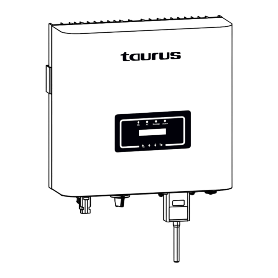
- Page 27 3.1 Interface View Normal Alarm Pic 3.1 Front panel display 3.2 Status Indicator There are four LED status indicator lights in the front panel of the inverter.Please see table 3.1 for details. status Inverter detects DC input ●DC Low DC input voltage Grid Connected ●AC Grid Unavailable...
- Page 28 Down Enter 3.4 LCD Display The two-line Liquid Crystal Display (LCD) is located on the front panel of the Inverter, which - 06 -...
- Page 29 sunlight or raining. ℃. - 07 -...
- Page 30 each inverter must be at least 500mm above and below.And must install the inverter at the place where children cannot touch. Please see picture 4.3. indicator status clearly. Safety Hint: ≤15° - 08 -...
- Page 31 Anchoring Stainless steel screws Inverter - 08 -...
- Page 32 accessory to lock inverter heat sink to the hanging plate, to ensure that the inverter will not move. - 09 -...
- Page 33 1. Switch the Grid Supply Main Switch(AC)OFF. 2. Switch the DC lsolator OFF. 3. Assemble PV input connector to the inverter. Safety Hint: cause serious damages to the inverter. Safety Hint: Safety Hint: within the 550V of the inverter. Pic 5.2 DC-connector (MC4) Safety Hint: Please use approved DC cable for PV system.
- Page 34 Pic 5.3 Disassemble the connector cap nut b) Crimping metal terminals with crimping pliers as shown in picture 5.4. Pic 5.4 Crimp the contact pin to the wire c) Insert the contact pin to the top part of the connector and screw up the cap nut to the top part of the connector.
- Page 35 , shown as picture 5.6 Warning: Sunlight shines on the panel will generate voltage, high voltage in series may panel needs to be blocked by the opaque material and the DC switch should be 'OFF', otherwise, the high voltage of the inverter may lead to life- AC side of the inverter, the AC side is equipped with single-phase AC terminals that can be Warning: Cable CSA...
- Page 36 body has two locking holes, and press the locking valve in the hole inward to separate the matching socket from the sleeve. 1. Matching socket 2.Sleeve 3.Sealing core 4.Sealing nut Pic 5.7 AC connector structure right length, as shown in Picture 5.8. 40mm 8~15mm Pic 5.8 Strip AC cable...
- Page 37 - 14 -...
- Page 38 all PE cables of the inverter need to be connected to the same grounding copper platoon to picture 5.11. Warning: than 300 mA or higher, otherwise inverter may not work properly. - 15 -...
- Page 39 prevent overcurrent. See table 5.3 below. 13.1 GPRS Web Server WIFI - 16 -...
- Page 40 plate as shown in Picture 5.13. When installing the datalogger, remove the sealing plate, and the inverter DC power on. When the inverter is on the DC power, it is determined whether Pic 5.13 D - 17 -...
-
Page 41: Startup And Shutdown
6. Startup and Shutdown connected to the same number of PV modules. 6.1 Start up the inverter When start up the single phase string inverter, should fellow below steps: 1. First switch on the AC breaker. voltage and power, the inverter will start. 3. - Page 42 connect the energy meter. For system wiring diagram, the red line refers to L line (L), the blue line refers to the neutral inverter's RS485 port. It's recommended to install an AC switch between the inverter and the The AC switch we recommend to connect to the inverter output can refer to Table 7.2. If there is no integrated DC switch inside the inverter you purchased, we commend you to connect the DC switch.
- Page 43 Normal Alarm Inverter Solar Panel array Grid meter VCC_5V 485_A 485_B Family load Warning: Ensuring grid input cables connect 1&3 port of energy meter, and inverter AC 1. Turn on the AC switch. picture 7.4. System Param << Island Param Meter OFF <<...
-
Page 44: Meter Power
6. If set up successfully, you can return to the menu interface, and display the LCD to [home Meter Power: inverter quickly according to the power of the user and solar panels, prevent the output of the inverter with limiter, a current sensor will be included in the package which is necessary for sensor to the inverter limiter interface. - Page 45 (The arrow of current sensor Pic 7.6 Sensor Clamp points to the grid) Sensor Load Grid Normal Alarm Solar Panel array 1. Turn on the AC switch. picture 7.9. << Fun GFDI System Param Param Limiter 0FF << Pic 7.9 Limit switch - 22 -...
- Page 46 be completed. Shown as picture 7.10. Fun GFDI Utility Power: Limiter ON << chapter 7.9. - 23 -...
- Page 47 Warning: inverter more responsive to limit the power. Safety Hint: (when using limiter, the arrow of current sensor points to the grid) - 24 -...
- Page 48 Up key and the Down key to see the current DC voltage, DC current, AC voltage, AC current, inverter. Devive LCD Main menu Time Fault Record Meter ImpEp System Param Run Param Setup Load Protect Param Start LoadEp Com. Param PV VA Grid and Fred E-Day and E-Total...
- Page 49 Power: Power: State: Standby State: Com.Error Press UP or Down, you can check inverter DC voltage, DC current, AC voltage,AC current and inverter temperature. PV1: 0.0V 0.0A Grid: 0V 0.0A Freq: 0.00Hz Pic 8.3 PV input voltage and current Pic 8.4 Grid voltage and frequency 21 - 05 - 2020 Meter 15 : 57 : 08...
- Page 50 Load Power: Pic 8.10 Load power LoadEp: 0.00KWh Total : 0.00KWh E-Day : E-Total : 134KWh 8.2 Submenus in the Main Menu Device Info. << GL1030 SN-01 Fault Record ID:0000000012 ID:0000000012 Ver0201 Ver1970 - 27 -...
- Page 51 8.2.2 Fault Record on the error code. Device Info. 1 F35 200521 15 Fault Record << 2 F56 200519 17 Pic 8.14 Fault Record ON / OFF << Turn ON << Setup Turn OFF Turn ON Turn OFF << Cancel <<...
- Page 52 param, comm: Setup << System Param << PV VA Param Protect Param Com. Param << Pic 8.17 Submenus of the parameter setup Time Set << Display Set Language Set Factory Reset << Pic 8.18 System Param 20200522 OK English << 08:11:21 Cancel Pic 8.19 Time Pic 8.20 Language...
- Page 53 8.4 Running param set Note: PassWord Pic 8.24Password ActiveP ReactiveP 0% << Pic 8.25 1.000 Fun ISO OFF << Pic 8.26 Fun RCD default value 60s SelfCheck 0s << Pic 8.27 Island meter,then set here to ON Meter OFF << Pic 8.28 - 30 -...
- Page 54 Limiter then set here to ON P.Factor 0.00 << Pic 8.29 MPPT Num turn on this item. WindTurbine << Pic 8.30 Those parameters is used for setup wind WindTurbine << trubine MPPT curve. Cancel 0.0V << DC1->Wind OFF << 0.0A DC2->Wind OFF <<...
- Page 55 00 INMETRO 00 EN50438 00 EN50549 << 00 IEC61727 << 00 CUSTOM Cancel << Note: Engineer only. AC OverVoltage << AC LowVoltage << 265.0V 185.0V AC OverFreq << AC LowFreq << 51.50Hz 47.50Hz Please set the proper grid parameters according to the requirements of your current country's 8.6 Com.
-
Page 56: Repair And Maintenance
9. Repair and Maintenance Warning: When the device is running, the local temperature is too high and the touch can maintain. Warning: No solvent, abrasive materials or corrosive materials can be used for cleaning any parts of the inverter. 10.1 Error code If there is any failure, the LCD screen will display an alarm message. - Page 57 1. Check PV panels connection and restart inverter. This DC insulation impedance problem is caused by the PV side usually; failure 2. If the fault still exists, please contact us for help. 1. Turn off the DC/AC switch and then wait 1~2 minutes, then AC main contactor failure turn on the DC/AC switch again;...
- Page 58 1. Check PV input voltage and Ubus voltage via LCD or monitoring platform; DC busbar voltage is too high 2. Disconnect DC switch and AC switch, and reconnect DC switch and AC switch 10min later to restart the inverter; 3. If the fault still exists, please contact us for help. 1.
- Page 59 IS1500M IS2600M IS3000M Input Side Start-up DC Input Voltage(V) 70~550 12.5 Output Side Rated Output Power(kW) Rated AC Grid Voltage(V) AC Grid Voltage Range(V) 160 ~300 (this may vary with grid standards) Single phase Rated AC Grid Output Current(A) 13.1 Output Power Factor 0.8 leading~0.8 lagging Grid Current THD...
- Page 60 Podrá encontrar el más cercano accediendo al Pour savoir lequel est le plus proche, vous pou- siguiente enlace web: http://taurus-home.com/ vez accéder au lien suivant : http://taurus-home. com/ También puede solicitar información relacionada poniéndose en contacto con nosotros por el telé- Vous pouvez aussi nous contacter pour toute information.
- Page 61 Poderá encontrar o mais próximo de si através do seguinte website: http://taurus-home.com/ Também pode solicitar informações relacionadas, pondo-se em contacto connosco. Pode fazer o download deste manual de instruções e suas atualizações em http://taurus- home.com/ Nederlands GARANTIE EN TECHNISCHE ONDERSTEU- NING Dit product valt onder de legale garantievoorwa- arden zoals bepaald in de actuele wetgeving.
- Page 62 COUNTRY ADDRESS PHONE Algeria Zone d'Activite, Nº 62, Constantine 213770777756 Argentina Av. del Libertador 1298,(B1638BEY), Vicente 541153685223 López (Pcia. Buenos Aires) Belgium Mariëndonkstraat 5, 5154 EG, Elshout 31620401500 Benin 359 Av. Steinmetz, 1930, Cotonou 0299-21313798 Bulgaria 35929211120 / 35929211193...
- Page 63 Gibraltar 11 Horse Barrack Lane, 54000, Gibraltar 00350 200 75397 / 00350 200 41023 Greece Sapfous 7-9, 10553, Athens +30 21 0373 7000 Guinea BP 206, GN, Conakry (224) 622204545 Hong Kong Unit H,13/F., World Tech Centre, Hong kong (852) 2448 0116 / 9197 3519 Hungary Késmárk utca 11-13, 1158, Budapest +36 1 370 4519...
- Page 64 Avda. Barcelona, s/n 25790 Oliana Spain...
Need help?
Do you have a question about the IS 3000 M and is the answer not in the manual?
Questions and answers