Advertisement
Quick Links
HARDWARE
INSTALLATION
MANUAL
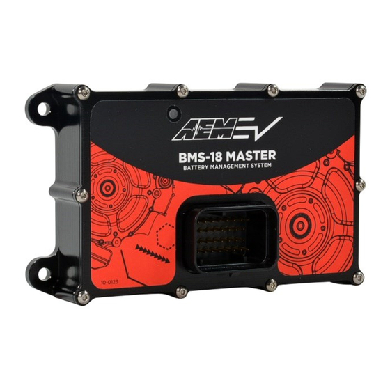
P/N 30-8401M & 30-8401S
18 CELL BMS MASTER MODULE
18 CELL BMS SATELLITE MODULE
STOP! - READ THIS BEFORE INSTALL OR USE!
WARNING:
IT IS THE RESPONSIBILITY OF THE INSTALLER TO ULTIMATELY CONFIRM THE
CONFIGURATION USED FOR ANY PARTICULAR INSTALLATION IS SAFE FOR ITS
INTENDED USE. AEM HOLDS NO RESPONSIBILITY FOR ANY DAMAGE THAT
RESULTS FROM THE MISUSEOF THIS PRODUCT.
Working on Electric Vehicle tractive systems with high voltage battery packs requires special experience
and training. Doing this safely is entirely the responsibility of the installer. AEM has done everything it can
to ensure the VCU has appropriate fault detection and failsafe logic but that does not mean that your
installation will be safe or that your VCU installation will not interfere with other systems on your vehicle and
create a hazardous situation. It is the responsibility of the installer to understand the implications of each
stage of tractive system installation and testing, and to know what might be unique about your application
that presents an unintended hazard or potential safety issue – and to solve it.
Following is a brief list of recommended practices. This is not a comprehensive list; as noted below, if you
are not well-versed in the appropriate installation and testing procedures, you should refer the installation
and calibration to a reputable installation facility or contact AEM EV for a referral in your area.
•
When access is required near the battery pack, the cell segments must be separated by using an
appropriate maintenance disconnect plug.
•
When working on the battery pack or tractive system, safety glasses with side shields and
appropriate insulated tools must be used.
•
Always wear Class 0 gloves rated at 1000V with leather protectors.
•
Only use a CAT III rated digital multi-meter (DMM) and test leads.
•
When working on the battery pack or tractive system, use the one hand rule: work with one hand
keeping the other behind your back whenever possible.
•
During initial system power up and testing, the vehicle must be raised off the ground and supported
appropriately. Wheels/tires should be removed.
•
During the VCU firmware upgrade process, battery cell segments must be separated by using an
appropriate maintenance disconnect plug.
•
Do not make calibration changes while the inverter PWM is enabled.
AEM Performance Electronics, 2205 126th Street Unit A, Hawthorne, CA 90250 - Phone: (310) 484-2322
http://www.aemelectronics.com
Advertisement

Related Manuals for AEM 30-8401M


Summary of Contents for AEM 30-8401M
- Page 1 Working on Electric Vehicle tractive systems with high voltage battery packs requires special experience and training. Doing this safely is entirely the responsibility of the installer. AEM has done everything it can to ensure the VCU has appropriate fault detection and failsafe logic but that does not mean that your installation will be safe or that your VCU installation will not interfere with other systems on your vehicle and create a hazardous situation.
- Page 2 Do not open the BMS Modules as high voltage may be present. If you suspect a Module may be damaged, immediately disconnect the unit and do not use it until it has been inspected by AEM. NEVER ATTEMPT TO USE A UNIT THAT YOU SUSPECT MAY HAVE BEEN DAMAGED.
- Page 3 Overview The AEM Battery Management System (BMS-18) hardware expansion for the AEM VCU is a modular BMS add-on designed for multicell lithium battery packs. The BMS allows the VCU to monitor all relevant Battery functions and adds the ability for the VCU to interface directly with a J1772 charging plug and allow the VCU to directly control a supported On-Board Charger (OBC).
- Page 4 216 cells and 36 temperatures. Another option available with the VCU-300 based systems is the ability to support 2 Masters, each with up to 5 satellites and have these monitoring parallel battery packs. Contact AEM before using multiple masters in this way.
- Page 5 Blanking Plug TE 4-1437284-3 A mating connector kit is available separately from AEM (P/N 30-3712, BMS-18 Plug & Pin Kit). It contains 1x mating connector, 34x terminals, and 10x blanking seals. Both the Master and the Satellite units use the same TE Superseal 34 pin connector and share the majority of their pin assignments.
- Page 6 BMS to wake up the VCU. This is needed since there are times when the VCU is asleep and the cockpit wake switch is off but the J1772 charging needs to wake up the VCU and initiate charging. This input should be 2024.04.12 – Document Number: 10-8401-EV © 2024 AEM Performance Electronics...
- Page 7 PE to the On-board Charger and you must also tee-off the PE connection to the vehicle ground as well or the Proximity signal will not read correctly. J1772 Charging Connections 2024.04.12 – Document Number: 10-8401-EV © 2024 AEM Performance Electronics...
- Page 8 The thermistors are wired to pins 19 & 27 for thermistor 1, pins 20 & 28 for thermistor 2 and pins 21 & 29 for thermistor 3. Polarity is unimportant. 2024.04.12 – Document Number: 10-8401-EV © 2024 AEM Performance Electronics...
- Page 9 Both the Master and Satellite are housed in sealed billet aluminum enclosures measuring 114mm x 71mm x 24mm not including the connector or mounting tabs. 3D models of the BMS modules are available by request from AEM. 2024.04.12 – Document Number: 10-8401-EV...
- Page 10 (1) your installation of any AEM products or (2) your misuse of any AEM products. In no event shall any AEM Party be liable to you or any...
- Page 11 Warranty returns will only be accepted by AEM Electronics when accompanied by a valid Return Merchandise Authorization (RMA) number and a dated proof of purchase. The product must be received by AEM Electronics within 30 days of the date the RMA is issued.
Need help?
Do you have a question about the 30-8401M and is the answer not in the manual?
Questions and answers