Table of Contents
Advertisement
Quick Links
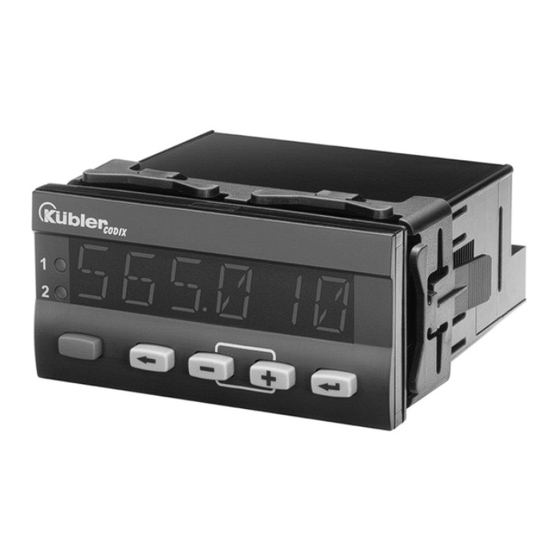
PMT565
for analog input signals
0 ... 10 V
2 ... 10 V
-10 ... + 10 V
0 ... 20 mA
4 ... 20 mA
Order code
PMT565 Process Monitor/Totalizer
Example:
PMT565
Series:
PMT565 = Process Monitor & Totalizer w/ 2 Presets/Relays
Operating Voltage:
0 = 100 to 240 VAC
3 = 10 to 30 VDC
Options:
0 = None
9 = Analog Output (only for DC version)
Accessories
NEMA4 wall mount enclosure available see LCN4X & MS821
Explosion proof enclosure available see XHV
RoHS Compliant
Toll Free: 800-631-2165.Phone: 732-935-1320.Fax: 732-935-9344
0
0
Kessler-Ellis Products
10 Industrial Way East, Eatontown, NJ 07724
www.kep.com
Process Controllers
for analog input signals with
Totalizer function
991025 05/22/19
Advertisement
Table of Contents

Related Manuals for Kessler-Ellis Products PMT565

Summary of Contents for Kessler-Ellis Products PMT565
- Page 1 4 ... 20 mA Order code PMT565 Process Monitor/Totalizer Example: PMT565 Series: PMT565 = Process Monitor & Totalizer w/ 2 Presets/Relays Operating Voltage: 0 = 100 to 240 VAC 3 = 10 to 30 VDC Options: 0 = None 9 = Analog Output (only for DC version) Accessories NEMA4 wall mount enclosure available see LCN4X &...
-
Page 2: Table Of Contents
Table of Contents Preface Safety instructions and Warnings Use according to the intended purpose Mounting in a control panel Electrical Installation Cleaning and maintenance Description Display/Operating elements Block diagram Connections Operating concept (Operating mode) Programming Function Groups Help Texts (running text) Signal inputs User Linearization Function Multifunction Key (MP-Key) and Multifunction inputs (MP-INP) -
Page 3: Preface
voltages at the terminals of the device must be kept Preface within the limits of Over-voltage Category II. The device must only be operated when mounted Please read this instruction manual in a panel in the correct way and in accordance entirely and carefully before installation with the section “Technical Data”. -
Page 4: Electrical Installation
Electrical Installation Before starting the device, check the cables for proper wiring and tightening. The screws of The device must be disconnected unused screw terminals must be screwed to the from any power supply prior to any stop, so that they cannot loosen and get lost. installation or maintenance work. -
Page 5: Description
Description Digital panel meter for displaying measured values, as well as monitoring limit values in industrial applications. 6-digit 14-segment LED display, 14 mm, for displaying measured values and • dialogs Running text can be switched on as Help Text • Language for the Help Text selectable as English or German •... -
Page 6: Block Diagram
Block diagram Connections Page 6... -
Page 7: Operating Concept (Operating Mode)
Operating concept (Operating mode) Page 7... -
Page 8: Programming
Programming To enter the Programming menu > 3 sec • During programming the relays are inactive (not energised). • When quitting the programming menu via SAVE, the minimum and maximum values and the Totalizer value are all cleared. Entering the Programming Menu / Selecting Function Group / Quitting the Programming menu Page 8... - Page 9 Selecting Function / Setting Parameters / Accepting Parameters Function Groups Function Parameter Page 9...
-
Page 10: Function Groups
Function Groups Select input high value Factory settings are highlighted grey. Input range depends on meas. range [V / mA] Select display high value for Help Texts (running text) INP.HI. Help Text menu Input range -199999 … +999999 and DP Select Help Text Select Input Filter The Filter function shows how... -
Page 11: User Linearization
User Linearization Input range depends on measuring range: Menu User Linearization 0 … 10 V = -0.500 … 10.500 [V] 2 … 10 V = 1.500 … 10.500 [V] Select User Linearization -10 … +10 V = -10.500 ... +10.500 [V] Linearisation OFF 0 …... - Page 12 Example for linear scaling Example 1: 0 … 10 V = 0 … 600 Example 2: 4 … 20 mA = 300 … 900 Example 3: 1.0 … 9.0 V = 750 … 400 Example for non-linear scaling Page 12...
-
Page 13: Function Multifunction Key (Mp-Key) And Multifunction Inputs (Mp-Inp)
Reset Totalizer Function Multifunction Key (MP-Key) and Multifunction In the function group MP.KEY, programme the inputs (MP-INP) function RES.TOT to ON. In the operating mode, select the Totalizer (TOTAL) and Tare briefly press the MP Key. In the function group MP.INP, programme the In the function group MP.KEY, programme the function MP.INP1 or MP.INP2 to RES.TOT. -
Page 14: Multifunction Key
9.4.1 Multifunction Key 9.4.2 Multifunction Inputs Menu Function MP-Key Menu Function MP-Inputs Select function: Select function MP-Input 1 Reset tare (TARA) value with No function MP-Key – only when current Reset MIN value measured value appears in the display Reset MAX value Reset MIN and MAX values Reset Output-Latch - only if output is in memory... -
Page 15: Totalizer Function
Totalize f r unction Select decimal point for Totalizer (optical function only) Menu Totalizer Select value for low threshold cut-off 0.00 0.000 Input value range 0.0000 -199999 … +999999 and DP 0.00000 Select value for multiplication factor The Totalizer function captures the current Input value range (instantaneous) measured value every 100 msec. -
Page 16: Limit Value (Alarm) Monitoring
Limit Value (Alarm) Monitoring Select Output triggering With incrementing measuring Menu Alarm Output 1 signal Select operating mode With decrementing measuring signal Band limitation Automatic operation Memory latch operation Select Alarm status - not with band limitation With alarm: output active Select source value for Alarm With alarm: output inactive output 1... - Page 17 Control with incrementing measuring signal Control with decrementing measuring signal Page 17...
-
Page 18: Monitoring Of Measuring Circuit
Control with Band Limitation 10 Monitoring of Measuring Circuit Lower Display Upper Display Lower Meas. Upper Meas. Probe or wire Range limit Range limit Range limit Range limit short-circuit Probe or wire break Meas. range 0 … 10 V – 2 …... -
Page 19: Technical Data
11 Technical Data 11.5 Supply voltage AC supply: 100 ... 240 V AC / max. 9 VA 11.1 General Data 50 / 60 Hz, Tolerance ± 10% Display: 6-digit, 14 segment LED ext. fuse protection: T 0.1 A Digit height: 14 mm DC supply: 10 ... -
Page 20: Connections
Shock resistance: EN60068-2-27 100G / XYZ 3 times in each direction EN60068-2-29 10G / 6 ms / XYZ 2000 times in each direction 11.11 Connections Supply voltage and outputs: Plug-in screw terminal, 8-pin, RM5.00 Core cross-section, max. 2.5 mm² Signal and control inputs: Plug-in screw terminal, 9-pin, RM 3.50 Core cross section, max. -
Page 21: Help Texts
13 Help Texts PROG. NO PROGRAMMING PROG. START PROGRAMMING HLP.TXT. MAIN MENU SELECT HELPTEXT HLP.TXT. HELPTEXTS ON HLP.TXT HELPTEXTS OFF SL.LANG. SPRACHE DEUTSCH SL.LANG. LANGUAGE ENGLISH INPUT. MAIN MENU SIGNAL INPUT RANGE 0-10V VOLTAGE INPUT RANGE 0-10V RANGE 2-10V VOLTAGE INPUT RANGE 2-10V RANGE -10.10V VOLTAGE INPUT RANGE -10V/+10V... - Page 22 MP.INP. MAIN MENU MP-INPUTS MP.INP.x NO.FUNC. NO FUNCTION MP.INP.x RES.MIN. FUNCTION RESET MIN VALUE MP.INP.x RES.MAX. FUNCTION RESET MAX VALUE MP.INP.x R.PEAKS FUNCTION RESET MIN/MAX VALUE MP.INP.x RES.REL. FUNCTION RESET OUTPUT-LATCH MP.INP.x DISP.HD. FUNCTION DISPLAY HOLD MP.INP.x LOC.ALR. FUNCTION LOCK EDITING ALARM VALUES MP.INP.x LOC.PRG.
Need help?
Do you have a question about the PMT565 and is the answer not in the manual?
Questions and answers