
Related Manuals for Samsung NZ30R5330RK


Summary of Contents for Samsung NZ30R5330RK
-
Page 1: Table Of Contents
RADIANT COOKTOP MODEL : NZ30R5330RK MODEL CODE : NZ30R5330RK RADIANT COOKTOP CONTENTS 1. General Specification 2. Installation 3. Features 4. Wiring Diagrams Disassembly and Reassembly 6. Troubleshooting Reference... - Page 2 • Contents 1. General Specification . . . . . . . . . . . . . . . . . . . . . . . . . . . . . . . . . . . . . . . . . . . . . . . . . . . . . . . . . . . . . . . . . . . . . . . . . . .4 1-1 Specification .
-
Page 3: General Specification
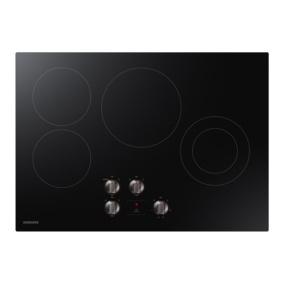
This document can not be used without Samsung’s authorization. 1. General Specification [General Specification] • 30” Radiant Cooktop • Cooking Zone Q'ty : 4EA • Total Power : 7,500W... -
Page 4: General Specification
This document can not be used without Samsung’s authorization. 1. General Specification 1. General Specification 1-1 Specification Basic Information New Model Model Information NZ30R5330RK Size 30" Color Black Design Frame Type Radiant Q'ty 4 EA Left Front 7" - 1500W Left Rear 7"... -
Page 5: Installation
This document can not be used without Samsung’s authorization. 2. Installation 2. Installation 2-1 Installation Install cooktop STEP 1 Prepare Installation Decide on the fial location for the cooktop. Avoid drilling or cutting into housewiring during installation. 1. Using 2 or more people, place the cooktop upside down on a covered surface using the foam end posts from the packaging. -
Page 6: Features
This document can not be used without Samsung’s authorization. 3. Features 3. Features 3-1 Features Cooking zones Left Rear Center Left Front (7",1500 W) (9", 2500W) (7",1500 W) Right Hot Surface Control Knob Indicator (5"/8",2000W) - Page 7 This document can not be used without Samsung’s authorization. 3. Features Knob lighting Press and turn the knob to a desired setting. The indicator turns on and confirms the selected setting. Single surface unit control knob 1. Push the knob in.
-
Page 8: Wiring Diagrams
This document can not be used without Samsung’s authorization. 4. Wiring Diagrams 4. Wiring Diagrams 4-1 Wiring Diagrams MODEL [MODELO] [MODÈLE] : NZ30R5330R* ENGLISH ESPAÑOL FRANÇAIS COLOR COLOR COULEUR ORANGE GREEN ROJO NARANJA VERDE ROUGE ORANGE VERT WHITE BROWN PINK BLANCO MARRÓN... -
Page 9: Disassembly And Reassembly
This document can not be used without Samsung’s authorization. 5. Disassembly and Reassembly 5-1 Tool for Assembly and Disassembly Item How to use Pictures Screw Driver(+) User for assembly and disassembly of all screws. Long Nose Plier Use for assembly and disassembly of wire terminal. -
Page 10: Assy Knob
This document can not be used without Samsung’s authorization. 5. Disassembly and Reassembly 5-2 Assy Knob Parts Explaination Photo Explaination 1Remove Assy Knob. Assy Knob ( Pull up the knob off the regulator shaft to remove) Assy Knob WARNING Disconnect power before servicing the range. Replace all panels before operating range. Failure to do so can result in death or electrical shock. -
Page 11: Assy Cover Back & Smps& Holder Pcb-Sub
This document can not be used without Samsung’s authorization. 5. Disassembly and Reassembly 5-3 Assy Cover Back & SMPS& Holder PCB-Sub Parts Explaination Photo Explaination Turn off the electrical power supply Assy Cover Back to the range. & SMPS& Holder... -
Page 12: Holder Pcb, Holder Hose Assy Wire Harness-Power Assy-Terminal Block
This document can not be used without Samsung’s authorization. 5. Disassembly and Reassembly 5-4 Holder PCB, Holder Hose Assy Wire Harness-Power Assy-Terminal Block Parts Explaination Photo Explaination Holder PCB, Holder Hose Assy Wire Assy Terminal block : Remove 4 Harness-Power... -
Page 13: Base Bottom
This document can not be used without Samsung’s authorization. 5. Disassembly and Reassembly 5-5 Base Bottom Parts Explaination Photo Explaination Base Bottom Remove the 4 screws from Base Bottom. Base Bottom Pass the Wire through Base Bottom Hole. -
Page 14: Cover Case, Support Frame, Cover Heater, Cover Display
This document can not be used without Samsung’s authorization. 5. Disassembly and Reassembly 5-6 Cover Case, Support Frame, Cover Heater, Cover Display Parts Explaination Photo Explaination Remove the 9 Screws inside of Cover Case. Cover Case Support Frame Remove the Support Frame and Cover Case, Cover Case. -
Page 15: Assy Cover Heater & Wifi & Assy Control Sub
This document can not be used without Samsung’s authorization. 5. Disassembly and Reassembly 5-7 Assy Cover Heater & Wifi & Assy Control Sub Parts Explaination Photo Explaination Remove 4 Screw from Assy Cover Adaibatic Assy Cover Heater and 1 screw from the Heater &... -
Page 16: Support Heater
This document can not be used without Samsung’s authorization. 5. Disassembly and Reassembly 5-8 Support Heater Parts Explaination Photo Explaination Support Heater Remove 4 screws from support heater. → Remove 4 screws and un- tie 2 cable clamps.. Remove Support Heater by sliding it to the Side. -
Page 17: Holder Support
This document can not be used without Samsung’s authorization. 5. Disassembly and Reassembly 5-9 Holder Support Parts Explaination Photo Explaination Assy Top Plate Remove Holder Support from Assy Top Plate. Holder Support It can be removed by taking off Holder Support from Assy Top Plate. -
Page 18: Bracket Spring
This document can not be used without Samsung’s authorization. 5. Disassembly and Reassembly 5-10 Bracket Spring Parts Explaination Photo Explaination Check assembly No. Remove Screw from Bracket Spring (Check number on heater) Bracket Spring Remove Wire harness from Heater. Single 1500W... -
Page 19: Assy Wire Harness-Main Assy Top Plate
This document can not be used without Samsung’s authorization. 5. Disassembly and Reassembly 5-11 Assy Wire Harness-Main Assy Top Plate Parts Explaination Photo Explaination Assy Wire Assy Wire Harness Harness-Main Remove Terminal wire from Heater. Assy Top Plate Assy Top Plate WARNING Disconnect power before servicing the range. -
Page 20: Troubleshooting
This document can not be used without Samsung’s authorization. 6. Troubleshooting 6. Troubleshooting 6-1 Parts Checking- Regulator wiring LEFT FRONT Position Color Yellow P1 : Red 2 : Orange 4 : Yellow Red+Red P2 : Black Orange Black LEFT REAR... -
Page 21: Reference
This document can not be used without Samsung’s authorization. 7. Reference 7. Reference 7-1 Checkpoints before service request SYMPTOM DIAGNOSIS REMEDY You may be using Use pans which are flat and match the diameter of the inappropriate cookware. surface unit selected. - Page 22 North & Latin America gspn3.samsungcsportal.com China china.samsungportal.com © Samsung Electronics Co., Ltd. March. 2019 This Service Manual is a property of Samsung Electronics Co.,Ltd. Printed in Korea Any unauthorized use of Manual can be punished under applicable International and/or domestic law.
Need help?
Do you have a question about the NZ30R5330RK and is the answer not in the manual?
Questions and answers