Table of Contents
Advertisement
WRT - Wireless Rotary Transducer
Model
WRT4-Hex1/4
WRT10-Hex1/4
WRT20-Hex 1/4
WRT25-Sq3/8
WRT75-Sq3/8
WRT180-Sq1/2
WRT500-Sq3/4
Download the latest version of this document at
http://www.desouttertools.com/info/6159990600_EN
Read all safety warnings and instructions
Failure to follow the safety warnings and instructions may result in
electric shock, fire and/or serious injury.
Save all warnings and instructions for future reference
Product Instructions
Part number
6152210510
6152210520
6152210530
6152210540
6152210550
6152210560
6152210570
WARNING
Printed Matter No. 6159990600_EN
Issue No.
01
Date
12/2023
Page
1 / 68
Advertisement
Table of Contents

Related Manuals for Desoutter WRT Series


Summary of Contents for Desoutter WRT Series
- Page 1 Printed Matter No. 6159990600_EN Issue No. Date 12/2023 Page 1 / 68 WRT - Wireless Rotary Transducer Product Instructions Model Part number WRT4-Hex1/4 6152210510 WRT10-Hex1/4 6152210520 WRT20-Hex 1/4 6152210530 WRT25-Sq3/8 6152210540 WRT75-Sq3/8 6152210550 WRT180-Sq1/2 6152210560 WRT500-Sq3/4 6152210570 Download the latest version of this document at http://www.desouttertools.com/info/6159990600_EN WARNING Read all safety warnings and instructions...
-
Page 2: Table Of Contents
Table of Contents Product Information .......................... 4 General Information......................... 4 Website .......................... 4 Information about spare parts .................... 4 Revision history........................ 4 Overview ............................ 4 General description ...................... 4 Product Description...................... 4 Dimensions .......................... 5 Weight .......................... 6 Battery.......................... 6 WLAN........................... 6 Technical Information...................... 7 Regulatory Domain ...................... 7 Storage and Use Conditions .................... 8 Accessories.......................... 9 User interface........................ 9 LED system.......................... 9... - Page 3 How to calibrate a tool with the Manual Adjustment ............ 41 How to navigate Results Database .................. 42 References ............................ 44 Operation types........................ 44 Test types........................... 52 Statistics types ........................ 56 Service.............................. 60 Diagnostic............................ 60 How to run a diagnostic...................... 60 How to download a diagnostic report ................. 61 How to print a diagnostic report .................. 61 How to check alarms status .................... 61 Maintenance.......................... 61 How to save results locally.................... 61...
-
Page 4: Product Information
► Save all Safety Information and instructions for future reference. ► Website Information concerning our Products, Accessories, Spare Parts, and Published Matters can be found on the Desoutter website. Please visit: www.desouttertools.com. Information about spare parts Exploded views and spare parts lists are available in Service Link at www.desouttertools.com. -
Page 5: Dimensions
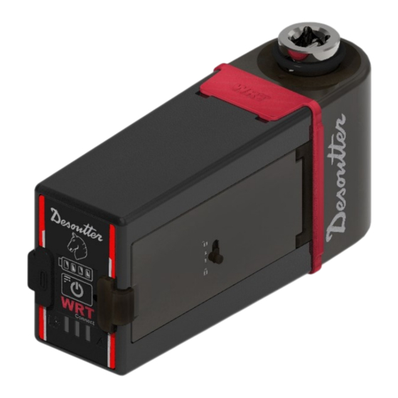
Product Information USB port cover User interface Battery cover clasp Battery cover lock lever Battery cover Transducer Dimensions Illustration 1: WRT4-Hex1/4, WRT10-Hex1/4, WRT20-Hex1/4 Illustration 2: WRT25-Sq3/8, WRT75-Sq3/8, WRT180-Sq1/2 6159990600 / v.01 5 / 68... -
Page 6: Weight
• Battery power supply: Rechargeable battery, Li-ion 3.635 VDC, 3.4 Ah • Full charging time: 5 hours • Battery life (tested at 6 tightenings per minute): 8 hours Use the Desoutter battery pack (P/N: 6159365310) only. WLAN • Type: IEEE 802.11b/g/n HT20; IEEE 802.11n HT40 •... -
Page 7: Technical Information
Product Information • 4900 ÷ 5975 MHz • Maximum conduct output power: • 18 dBm • 13.5 dBm • Maximum radiated output power: • IEEE 802.11b mode: 18.00 dBm • IEEE 802.11g mode: 18.43 dBm • IEEE 802.11n HT20 mode: 18.58 dBm •... -
Page 8: Storage And Use Conditions
Product Information 2.4 GHz authorized channel list per regulatory domain Channel FCC America ETSI Europa Worldwide 5 GHz authorized channel list per regulatory domain Channel Radio Band FCC North America ETSI Europa Worldwide U-NII-1 U-NII-2 U-NII-2e Storage and Use Conditions •... -
Page 9: Accessories
6159364610 WRT 2x Adapters 6159365340 Use the Desoutter battery pack (P/N: 6159365310) only. User interface The WRT User Interface consists of one physical ON/OFF button and of a LED system that communicates to the user the device status and the tests' results. -
Page 10: Usb Port
The USB type-C port is available for the WRT first configuration and for charging the device battery. The USB type-C port is also used for firmware upgrade (reserved to authorized Desoutter Service Personnel). It is recommended to use the dual screw USB Type-C locking plug connector supplied with the WRT. Make sure to fasten the two screws until the plug is properly locked to the USB port. -
Page 11: Installation
Installation Installation Installation Instructions How to install the battery On the battery cover (1), slide the lock lever (2) and keep it still to unlock the clasp (3) that secures the cover to the body of the device. Then, open battery cover. Insert the battery (4) into the battery compartment (5) starting with the side facing the WRT user interface (6). -
Page 12: How To Turn On/Off The Wrt
Installation It is recommended to use dual screw USB Type-C locking plug connector supplied with the WRT. Make sure to fasten the two screws until the plug is properly locked to the USB port. When the WRT is in standby mode and charging via USB cable, by default all Battery LEDs are off. To verify the battery level, press the ON/OFF button once. -
Page 13: How To Connect The Wrt To The Web User Interface
Installation Turning off the WRT On the WRT user interface, press the ON/OFF button (2) until the Horse LED (1) turns on. As soon as the Horse LED turns on, release the ON/OFF button. Turning off the WRT On the WRT user interface press the ON/OFF button (2) until all LEDs turn off. How to connect the WRT to the Web User Interface Turn on the WRT. - Page 14 Installation Production Administra- manager/ Maintenance tor/ Desoutter No session Operator Q&A user operator 3rd lab user Technician View current language View Wi-Fi connection status View battery level Use Virtual Assistant for configuration Read Identification infor- mation Read calibration certifi- cate...
- Page 15 Installation Production Administra- manager/ Maintenance tor/ Desoutter No session Operator Q&A user operator 3rd lab user Technician View operations configu- ration Add a new operation Edit an existing operation configuration Remove an existing oper- ation Start operation Enable/disable Demo Locked to...
-
Page 16: Initial Configuration
Installation Production Administra- manager/ Maintenance tor/ Desoutter No session Operator Q&A user operator 3rd lab user Technician Export Log files Print Log files Delete Log files Save locally results and configuration Delete all operations Delete all results Delete all curves... -
Page 17: How To Configure The Wrt Using The Virtual Assistant
Installation Upload calibration certificate Calculate the calibration value Start a new calibration operation View curve Upload file Edit View details View notifications Wi-Fi connection on Wi-Fi connection off Device set up as access point - no client connected Device set up as access point - one client connected Ethernet over USB connection on No connected device found Action required... -
Page 18: How To Upgrade The Application Firmware
Installation In the category of the selected Operation type, click Edit to configure the demo test, or click Run run the test using the default settings. For more information on how to configure a demo test, refer to How to edit a demo test [Page 24] and to Demo test parameters [Page 24]. - Page 19 Installation Next to Upgrade WiFi, click Attach and browse the .rps file containing the Wi-Fi firmware upgrade. Next to Upgrade WiFi, click Upgrade. In the confirmation dialog, click Yes. Do not refresh the Web User Interface page and do not disconnect the WRT while uploading the upgrade file, otherwise the operation will fail.
-
Page 20: Operation
Operation Operation Configuration Instructions How to configure the WRT Actions and features described in this section might require permissions assigned only to specific user roles. For more information, refer to User roles and permissions [Page 13]. How to view WRT information On the Web User Interface Navigation menu, click Identification. - Page 21 Operation Calibration Report History category The Calibration Report History category lists the calibration reports stored in the device. The list is defined by the following columns: Index number of the calibration report. Index Date when the calibration report has been uploaded. Upload date Comment Additional comment left by the operator.
- Page 22 Operation How to edit General Settings On the Web User Interface Navigation menu, select General Settings and edit the settings as required: Parameter Description Device description Type a name for the connected WRT. Unit In the drop-down list, select the default unit of measurement for operations from the following options: •...
- Page 23 Operation Under WiFi mode, in the drop-down list select a Wi-Fi mode for the connected device from the following op- tions: Mode Description Disabled Disable the Wi-Fi module of the connected device. Infrastructure mode Set up Wi-Fi connection using the local network. Access point mode Set up the WRT as access point for Wi-Fi connection.
-
Page 24: How To Configure Demo Tests
Operation Parameter Description Network name (SSID) Type the name of the network. Security type In the drop-down list, select the security type to apply to the wireless network. Encryption type In the drop-down list, select the encryption type to apply to the wireless network. Security key Type the network password (minimum length: 8 characters). - Page 25 Operation The availability of parameters depends on the selected Operation type. Editable parameters Available with Parameter Description operation types: Max torque Type the torque upper limit value to get an OK result. Click wrench Nutrunner Peak Pulse tool Min torque Type the torque lower limit value to get an OK result.
- Page 26 Operation Available with Parameter Description operation types: Frequency cut Select the frequency cut to be applied to the torque samples measured by the WRT. Click wrench Nutrunner Peak Pulse tool Peak monitor Select the requisites for a peak to be considered the test result: Nutrunner •...
-
Page 27: How To Configure Tools
Operation Parameter Description Second threshold According to the selected strategy, this threshold is used to exclude from the analysis the part of the curve below a certain value in order to detect either the proper torque peak or the proper click point. Set value depends on the selected Operation type. -
Page 28: How To Configure Operations
Operation Parameter Description Unit In the drop-down list, select the unit of measurement to use from the following options: • Nm • kg/m • kg/cm • lb/ft • lb/in • oz/ft • oz/in • kPm • dNm Relevant Information 2 Operation types [44] How to delete a tool On the Web User Interface Navigation menu, click Operations. - Page 29 Operation Operation parameters Controls category Parameter Description Operation name Assign a name to the operation. Operation type This parameter is automatically configured according to the selected Tool type. If the selected Tool type is set to Nutrunner or Peak, it is also possible to set the Operation type to Free Angle.
- Page 30 Operation Available with Parameter Description operation types: Min torque Type the torque lower limit value to get an OK result. Click wrench Nutrunner Peak Pulse tool First threshold According to the selected Operation type, this threshold is used to detect either the Click wrench torque peak value or the click point of a wrench.
- Page 31 Operation Available with Parameter Description operation types: Peak monitor This parameters defines the requisites for a peak to be considered as a result. Select a Click wrench peak monitor from the following options: Nutrunner • Peak Click: the first peak (click point) is considered as result of the test. This value is available only for Click wrench operation type.
-
Page 32: Operating Instructions
Operation Available with Parameter Description operation types: Batch size Type the number of times the test must be run in the batch, or use the up- and down- Click wrench arrow to respectively increase or decrease the value. Nutrunner The maximum value is 99. For Free angle strategy Batch size must be between 10 and Peak Pulse tool Free angle... -
Page 33: How To Run An Operation
Operation On the Demo mode menu, select the Operation type of interest to expand the category. The available operation types are the following: • Click wrench • Nutrunner • Peak • Pulse tool • Free angle In the category of the selected operation type, select the checkbox In the left panel of the Operations page, click Start Operation and perform the demo test. - Page 34 Operation Position Name Description Sidebar Select the tabs on the sidebar to display their respective content: • General results - displayed by default in the upper section of the left panel (posi- tion B). • Torque statistics - displayed in the upper section of the left panel (position B). •...
- Page 35 Operation The General results information is displayed by default when opening the Live Results page. To select it man- ually, select General result on the sidebar. Relevant Information 2 Operation parameters [29] 2 Tool parameters [27] Torque statistics On the Web User Interface Navigation menu, select Live results. On the sidebar, select Torque statistics.
- Page 36 Operation The top section of the Live Results page's left panel displays the Angle statistics calculated for the current opera- tion. Angle statistics information differs according to the Statistics type set for the operation. CNOMO statistics information: Minimum angle value measured in the operation. Maximum angle value measured in the operation.
- Page 37 Operation Control Chart On the Web User Interface Navigation menu, select Live Results. The bottom section of the Live Results page's left panel displays a Control chart of the ongoing operation, which is updated in real time: Position Name Description Upper limit.
- Page 38 Operation 1. Example of Result Dashboard for a Nutrunner operation 2. Example of Result Dashboard for a Pulse tool operation with batch complete. with batch incomplete. Position Name Description Operation result Color of the area indicates the result of the operation based on the tests run so far: •...
- Page 39 Operation Area Information Torque result • Torque value measured during the test. • Minimum torque value measured in the operation so far. • Maximum torque value measured in the operation so far. • Average torque value measured in the operation so far. •...
- Page 40 Operation • Frequency: measured frequence of the pulse tool under test. This column is available only for operations with Operation type set to Pulse tools The torque and angle results values are marked with colors according to how the values are positioned in relation to the upper and lower limits set for the operation: •...
-
Page 41: How To Calibrate A Tool With The Manual Adjustment
Operation Peak Requisite for a peak to be considered as a result. Start torque Torque value from which the test started. Torque value from which the angle measurement started. Angle threshold Lower limit torque value to get an OK result. Min torque Max torque Upper limit torque value to get an OK result. -
Page 42: How To Navigate Results Database
Operation Select a suitable Pset on the external controller. Perform a tightening. In the Results List, under the System Torque column click Edit in the row of the result you just collected, and enter the torque value displayed on the external controller screen. Then, press Enter on your keyboard to confirm. - Page 43 Operation Name Description Result ID Progressive ID number assigned by the system to each test result. The result ID label also shows the result status • If green with the OK icon , the results is ok according to the operation configuration. •...
-
Page 44: References
Operation How to download stored results On the Web User Interface Navigation menu, select Results Database. In the upper-right corner of the page, click Download . In the Separators dialog, select from the drop-down list a separator for the cvs format. Click Confirm. - Page 45 Operation • End time: timer that determines the end of a test. After detecting the peak value, if the torque decreases and re- mains below the transducer minimum load value (usually 10% of the transducer full scale) for a time equal or longer than the End time value, the test ends.
- Page 46 Operation False click that could be detected as click point 1st threshold that could be decreased to make sure to detect the real click point. Setting the 1st threshold value too low increases the risk of detecting false click points, while setting this value too high increases the risk of not detecting the real click point.
- Page 47 Operation Point considered as result if Peak monitor is set to Absolute Click. Relevant Information 2 CNOMO standard's formulas [56] 2 ISO standard's formulas [58] Peak A Peak operation detects the maximum torque measured during a test. Illustration 12: Torque vs. Time Peak The default Filter frequency for Peak operations is 100 Hz.
- Page 48 Operation Illustration 14: Torque vs. Time Peak torque The default Filter frequency for Nutrunner operations is 500 Hz. In case of multiple peaks, the result depends on the configuration of the operation. The parameters that characterize the peak detection are the following: •...
- Page 49 Operation • 1st threshold and 2nd threshold: depending on the value set for Peak monitor, the thresholds have different ap- plications: • With First Peak as Peak monitor, 1st threshold and 2nd threshold serve to detect the peak point. For a peak to be considered the result fo the test, the torque value must continuously decrease from the mea- sured peak at least till the 1st threshold value.
- Page 50 Operation peak is not considered a click point. Meanwhile, all torque values below the 2nd threshold are not taken into account in order to exclude noise that might interfere with the peak detection. If the last peak is below the 2nd threshold, it is not detected.
- Page 51 Operation Illustration 23: Torque vs. Time Peak torque Bounces • Torque factor K: coefficient used to adjust the torque measured by the transducer to match the real torque gener- ated on a joint by a pulse tool. Pulse tools do not provide a continuous torque output, instead they generate a single high energy pulse with a very short duration (≈1ms).
-
Page 52: Test Types
Operation Free Angle A Free Angle operation measures the angle value while monitoring it stays within the tolerance limits set for the op- eration. The parameters that characterize tests with Free angle strategy are the following: • Max angle: angle upper limit value to get an OK result. •... - Page 53 Operation The other SPC test limits are calculated as follows: Upper Control Limit Lower Control Limit Upper Warning Limit Lower Warning Limit Range In these formulas, A and D are coefficients that depend on the number of SPC tests performed: Number of SPC tests 0.000 0.000...
- Page 54 Operation Tool usability: Tool can be used. Diagnosis: The average is lower than the lower control limit, but it does not fall under the lower tolerance limit. Further actions: Calibrate increasing the torque. • Dispersion is too large Dispersion is considered too large when the difference between the maximum and minimum value is greater than the Range (see Range formula above).
- Page 55 Operation Tool usability: Tool can be used. Diagnosis: Averages are lower than the target value, but they do not fall under the lower tolerance limit. Further actions: Calibrate increasing the torque. • Last 7 averages are increasing or decreasing Tool usability: Tool can be used. Diagnosis: Averages tend to be higher than the target value, but they do not exceed the upper tol- erance limit.
-
Page 56: Statistics Types
Operation Cm/Cmk test The Cm/Cmk test assesses the capability of a tool in terms of tool's repeatability and accuracy in operations. The test analyzes the tool's collected results in relation to a tolerance range defined by an upper limit and a lower limit. - Page 57 Operation Coefficient for a 95% confidence threshold Instantaneous dispersion: D Process capability: CAM Where Tolerance Interval = max tolerance - min tolerance. Testing the homogeneity of the population Each sample of measurements W must comply with: Standard deviation: σ Where the population mean ( ) is: Population value.
- Page 58 Operation Number of samples Coefficient C 1.24 1.22 1.21 1.19 1.18 1.17 1.17 1.16 1.15 1.15 1.14 1.14 20 to 22 1.13 23 to 25 1.12 26 to 31 1.11 32 to 35 1.10 36 to 44 1.09 45 to 51 1.08 Coefficient of position and dispersion: Cpk The station is “capable”...
- Page 59 Operation Tolerance Interval = max tolerance - min tolerance. σ Standard deviation Coefficient of position and dispersion: C 6159990600 / v.01 59 / 68...
-
Page 60: Service
Service Service Diagnostic How to run a diagnostic To perform the following operation, the WRT battery charge level must be above 15%. On the Web User Interface Navigation menu, select Diagnostic. In the left panel of the Diagnostic page, click Launch Diagnostic. The diagnostic procedure must be performed until the end without turning off the device. -
Page 61: How To Download A Diagnostic Report
Service The WRT can store up to 10 diagnostic reports. If there are already 10 stored diagnostic reports and a new diag- nostic is run, the oldest report is automatically deleted to be replaced by the new diagnostic report. To navigate the stored reports, use the numbered list at the top of the Diagnostic page's right panel. Reports are sorted from newest to oldest. -
Page 62: How To Reset The Device To Factory Settings
Service In the left panel of the Maintenance page, in the Memory operation category, look for the item Delete all curves and results. Next to Delete all curves and results, click Delete. In the confirmation dialog, click Yes to confirm the operation. The number reported in square brackets after Delete all curves and results is the number of curves and results currently stored in the device. -
Page 63: How To Print Log Files
Preventive Maintenance Calibration The WRT - Wireless Rotary Transducer must be calibrated at least once a year. Contact Desoutter Service for cali- bration. Cleaning Keep the WRT - Wireless Rotary Transducer clean. - Page 64 Service Use an anti-static cleaning cloth in order to remove dust from the WRT - Wireless Rotary Transducer. Avoid using harsh detergents to clean the WRT - Wireless Rotary Transducer. Clean the contact of the WRT - Wireless Rotary Transducer by using an electrical contact cleaner solution. 64 / 68 6159990600 / v.01...
-
Page 65: Recycling
Recycling Recycling Environmental Regulations When a product has served its purpose it has to be recycled properly. Dismantle the product and recycle the compo- nents in accordance with local legislation. Batteries shall be taken care of by your national battery recovery organization. Recycling information Part Recycle as... - Page 66 Recycling Part Recycle as Transducer Steel Ringnut Aluminum Body Aluminum Bearing Steel Magnetic Ring Steel Main PCB WEEE 66 / 68 6159990600 / v.01...
- Page 68 Original instructions Founded in 1914 and headquartered in France, Desoutter Industrial Tools is a global leader in electric and pneumatic assembly tools serving a wide range of assembly and manufacturing operations, including Aerospace, Automotive, Light and Heavy Vehicles, Off-Road, General Industry.
Need help?
Do you have a question about the WRT Series and is the answer not in the manual?
Questions and answers