Table of Contents
Advertisement
Quick Links
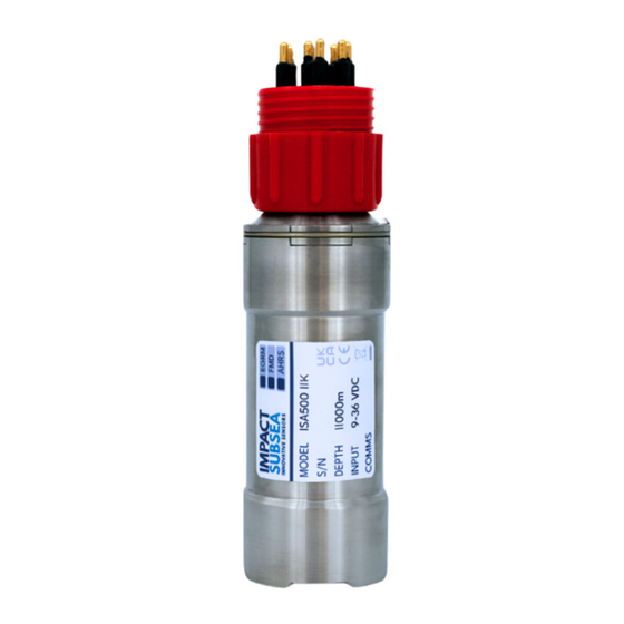
ISA500
Underwater Altimeter & Echosounder
Installation & Operation Manual
Revision Number:
2.9
th
Date
24
April 2024
+44 (0) 1224 460 850 | info@impactsubsea.co.uk | impactsubsea.com
I
mpact Subsea Ltd, Company Number: SC498003, Registered in Scotland,
Registered Office: Silverfield House, Aberdeen Energy Park, Claymore Drive, Bridge of Don, Aberdeen, AB23 8GD, UK.
Advertisement
Table of Contents

Related Manuals for Impact Subsea ISA500


Summary of Contents for Impact Subsea ISA500
- Page 1 ISA500 Underwater Altimeter & Echosounder Installation & Operation Manual Revision Number: Date April 2024 +44 (0) 1224 460 850 | info@impactsubsea.co.uk | impactsubsea.com mpact Subsea Ltd, Company Number: SC498003, Registered in Scotland, Registered Office: Silverfield House, Aberdeen Energy Park, Claymore Drive, Bridge of Don, Aberdeen, AB23 8GD, UK.
-
Page 2: Table Of Contents
3.2.3 Alignment with Vehicle (Pitch/Roll Accuracy) ..............12 3.2.4 Heat Sources (Temperature Accuracy) ................12 3.3 Mounting ............................. 13 Operation ............................14 4.1 ISA500 Configuration & Use with seaView software ..............14 4.2 Integration with Systems ......................16 4.3 Understanding advanced features ..................... 17 Servicing ............................18 Document No: 0000.1905 | Version No: 2.9 | 24... - Page 3 Output Strings..........................19 6.1 Altitude ............................19 6.2 AHRS ............................26 Theory of Operation ........................33 7.1 Altitude - Basic Principles ......................33 7.2 The Sonar Equation ........................35 7.2.1 Source Level (SL) ........................ 35 7.2.2 Transmission Loss (TL) ....................... 36 7.2.3 Noise Level (NL) .........................
-
Page 4: Introduction
Utilising a broadband composite transducer and advanced digital signal processing techniques; enables the ISA500 to achieve long range capability with a high degree of accuracy and stability. Ranges in excess of 120 meters are achievable as are 1mm accuracy range measurements. -
Page 5: Specification
2.0 Specification 2.1 Overview ISA500 (Forward Looking, Titanium Housing) ISA500 (Right Angle, Acetal Housing) 2.2 Dimensions 2.2.1 Forward Looking Housing 2.2.2 Right Angle Housing All dimensions given in mm. Document No: 0000.1905 | Version No: 2.9 | 24 April 2024... -
Page 6: Acoustic, Heading, Attitude & Temperature
Input Voltage 9 to 36V DC Power (No Altitude) 26mA @ 24V DC * Not available in all ISA500 Altimeters – check at time Power (With Altitude) 52mA @ 24V DC ** of ordering. ** 100% Tx power, 10Hz update rate Document No: 0000.1905 | Version No: 2.9 | 24... -
Page 7: Installation
3.0 Installation 3.1 Electrical Installation The ISA500 is fitted with a SubConn MCBH8M-SS connector as standard. This will mate to a SubConn MCIL8F connector/cable assembly. Other connector options are available upon request. 3.1.1 Connector Pin Out The standard connector pin out is provided below:... -
Page 8: Power
3.1.2 Power The ISA500 is polarity protected and fused with a 400mA resettable poly fuse. Internal circuitry isolates the supply from the outside environment requiring the serial interface, TTL trigger and analogue output to use the digital and analogue 0V reference pin. -
Page 9: Rs485 Wiring
3.1.5 RS485 Wiring The RS485 termination resistor is software selectable. Note: The digital 0V must be connected on an RS485 interfaces, otherwise the voltage potential between one of the A+ or B- lines to ground could reach a damaging level Document No: 0000.1905 | Version No: 2.9 | 24 April 2024... -
Page 10: Analogue Out And Ttl Trigger
The Analogue interface can be configured to output voltage or current (current option is not available on all ISA500 sensors). It is isolated from the supply and has in-line fused protection. A prolonged transient voltage on this line will blow the surface mount fuses... -
Page 11: Establishing Communications
3.1.7 Establishing Communications If the ISA500 is tilted from vertical to upside down 3 times within the first 10 seconds of applying power then it will temporarily configure the serial interface to (RS232, 9600, N81) and output an ASCII message displaying the settings. -
Page 12: Location
ISA500 settings in seaView to see the various settings which can be adjusted. 3.2.2 Magnetic Disturbers (Heading Performance) Where the heading output is to be used, the ISA500 should be mounted as far as possible from sources of magnetic interference. -
Page 13: Alignment With Vehicle (Pitch/Roll Accuracy)
3.2.4 Heat Sources (Temperature Accuracy) In order for the ISA500 to read the ambient temperature of the water, it should not be installed in close proximity of any heat sources (such as Hydraulic Power Packs). -
Page 14: Mounting
ISA500. The ISA500 has two flats, on either side of the body – these are to enable the unit to sit tightly against another flat surface if available. These flats also help prevent the unit moving when on the workbench for testing. -
Page 15: Operation
1.9.2 or only earlier. If you would like to upgrade the firmware of your ISA500 to version 3.0 or newer, please contact Impact Subsea support. Please note that if upgrading to firmware V3.0 or newer, the firmware cannot be downgraded again. - Page 16 V3.0 ISA500 Application seaView V1.9.0 ISA500 Application Document No: 0000.1905 | Version No: 2.9 | 24 April 2024...
-
Page 17: Integration With Systems
Autonomous mode will make a measurement and output the result over serial or analogue at a specified time interval. The ISA500 can be configured to operate in one or both of these modes at the same time. ISA500's with the AHRS option make use of the same interrogated and autonomous mechanises to output heading pitch and roll data over the serial interface. -
Page 18: Understanding Advanced Features
The energy level ranges from 0 to 1 where 1 represents full saturation of the ISA500 receiver. An energy level of 0.707 (square root of 2) is the theoretical perfect level as it represents the energy of a pure sine wave with an amplitude utilising the maximum dynamic range of the ISA500. -
Page 19: Servicing
The unit should be stored in its original case, in a cool, dry place. It is recommended that the unit be returned to Impact Subsea Ltd, on an annual basis to have a health check and service conducted. Document No: 0000.1905 | Version No: 2.9 | 24... -
Page 20: Output Strings
6.0 Output Strings The string IDs below are for ISA500 firmware version 3.0 and above. number shown in brackets after the IDXXX (X) is the ID of the string in firmware earlier than version 3.0. If there is no number in brackets, the string is only available from firmware version 3.0 onwards. - Page 21 ID104 (4): Impact Subsea multi echo output with signal level, correlation and temperature $ISAMI,tt.t,C,ddd.ddd,e.eeee,c.cccc,...,...,...*xx<CR><LF> Temperature in Celsius tt.t Distance in meters from the transducer face to the target ddd.ddd Energy level (0 to 1) e.eeee Correlation factor (0 to 1) c.cccc...
- Page 22 Distance in meters from the transducer face to the target dd.dd ID114 (14): Ulvertech Bathy 00000,dddd<CR><LF> Distance in centimetres from the transducer face to the target dddd ID115 (15): Impact Subsea time and temperature $ISATS,dddddd,us,tt.t,C*xx<CR><LF> Time in micro seconds to target dddddd Temperature in Celsius tt.t NMEA standard checksum Document No: 0000.1905 | Version No: 2.9 | 24...
- Page 23 NMEA standard checksum Example string format for 3 echoes (Note: 10 echoes maximum number of multi echoes output via ASCII string): $ISAMD,tt.t,C,dddddd,dddddd,dddddd*xx<CR><LF> ID118 (18): Impact Subsea temperature and multi echo (time) with energy and correlation $ISAMV,tt.t,C,dddddd,e.eeee,c.cccc,...,...,...*xx<CR><LF> Temperature in Celsius tt.t Time in micro seconds to target.
- Page 24 ID119 (19): NMEA $SDDBT $SDDBT,a.a,f,b.b,M,c.c,F*hh<CR><LF> Distance in feet from the transducer face to the target Distance in meters from the transducer face to the target Distance in fathoms from the transducer face to the target Checksum delimiter Checksum field <CR><LF> End of sentence carriage return and line feed characters ID120 (20): NMEA $SDDPT $SDDPT,x.x,x.x*hh...
- Page 25 Impact Subsea Binary multi echo data (ID22): Binary data frame containing a list of up to 100 multi echo outputs. The frame is COBS encoded, has a CRC16 checksum and uses 0x00 as a frame delimiter.
- Page 26 After the ID (0x10) is an array of 32 bit floats representing each echo’s distance in meters to the target, normalised correlation factor (0.0 to 1.0) and normalised energy level (0.0 to 1.0). Document No: 0000.1905 | Version No: 2.9 | 24 April 2024...
-
Page 27: Ahrs
6.2 AHRS ID131 (1): Impact Subsea heading, pitch, roll $ISHPR,hhh.h,spp.p,srrr.r*xx<CR><LF> sign + or - heading in degrees (0 to 359.9) hhh.h pitch in degrees (90.0 to -90.0) pp.p roll in degrees (180.0 to -180.0) rrr.r NMEA standard checksum ID132 (2): Impact Subsea quaternion Quaternions represent the orientation of a 3D body in a 4 dimensional world. - Page 28 All values are floating point numbers. Sign only shown if negative Accelerometer data is provided in G Gyroscope data is provided in degrees per second Magnetometer data is provided in micro Tesla ID134: Impact Subsea heading, pitch, roll, accelerometer, gyro, magnetometer $ISALL,hhh.h,spp.p,srrr.r,a.aaa,a.aaa,a.aaa,g.ggg,g.ggg,g.ggg,m.mmm,m.mmm,m.mm m*xx<CR><LF> sign + or - heading in degrees (0 to 359.9)
- Page 29 ID135: Impact Subsea w,x,y,z,accelerometer, gyro, magnetometer $ISQUR,w,x,y,z,a.aaa,a.aaa,a.aaa,g.ggg,g.ggg,g.ggg,m.mmm,m.mmm,m.mmm*xx<CR> <LF> floating point number Q0 floating point number Q1 floating point number Q2 floating point number Q3 Accelerometer reading: X then Y then Z a.aaa Gyroscope reading: X then Y then Z g.ggg magnetometer reading: X then Y then Z m.mmm...
- Page 30 ID137: TOKIMEK2 $PTVF,appp.ppP,brrr.rrR,hhh.hT,fgg.gPR,hii.iRR,jkk.kAR,lmm.mN,yyyMD,zzzzAL*nn<CR> <LF> [-] stern down; [space] bow down pitch in degrees (90.00 to -90.00) ppp.pp [-] starboard down; [space] port down roll in degrees (90.00 to -90.00) rrr.rr heading in degrees (0 to 359.9) hhh.h [-] stern down; [space] bow down rate of pitch in degrees/second gg.g [-] starboard down;...
- Page 31 ID138: Watson I hhh.hh arrr.r bppp.p cggg.g dkkk.k hiii.i 0000.0 <CR><LF> heading in degrees (0 to 359.99) hhh.hh [-] starboard down / [+] port down Roll rate in degrees per second rrr.r [-] stern down / [+] bow down Pitch rate in degrees ppp.p [-] heading increasing / [+] heading decreasing heading rate in degrees...
- Page 32 ID141: TSS1 :aaaabbbb 0000U rrrrr ppppp<CR><LF> Horizontal acceleration aaaa Vertical acceleration bbbb Roll in degrees * 100 (9000 to -9000) rrrrr Pitch in degrees * 100 (9000 to -9000) ppppp ID142: CDL TOGS AHhhh.hh APbpp.pp ARdrrr.rr Mf Eggggggg Sx Cyyyy<CR><LF> Heading in degrees hhh.hh [-] bow down [+] stern down...
- Page 33 ID145: Seapath $PSXN,rrr.rr,pp.pp,hhh.hh, aa.aa*xx <CR><LF> roll in degrees (180.0 to -180.0) rrr.rr pitch in degrees (90.0 to -90.0) pp.pp heading in degrees (0 to 359.9) hhh.hh vertical acceleration in m/s^2 aa.aa NMEA standard checksum Document No: 0000.1905 | Version No: 2.9 | 24 April 2024...
-
Page 34: Theory Of Operation
ISA500. This reflected portion is detected by the ISA500 and the time taken for this acoustic pulse to travel from the ISA500, bounce off the seabed and return is recorded. - Page 35 1,500m/s. For example, if an acoustic pulse takes 0.1 seconds to return to the ISA500 after being sent, we can calculate its round-trip travel distance as: Distance = Speed x Time = 1,500 x 0.1...
-
Page 36: The Sonar Equation
7.2 The Sonar Equation Any equipment which relies on acoustics underwater for ranging purposes, falls into the category of a Sonar, and hence the operation is governed by the 'Sonar Equation'. A clear understanding of this equation is essential in the design of any acoustic equipment, and useful to have an understanding of for those wishing to utilise acoustic equipment to its full potential. -
Page 37: Transmission Loss (Tl)
7.2.2 Transmission Loss (TL) As the acoustic pulse propagates through the water, it experiences spreading, which causes the energy of the signal to be dispersed over an ever-increasing area. This diminishes the energy at any specific point as distance increases. The acoustic pulse will also experience absorption by the water. -
Page 38: Directional Index (Di)
An appreciation of the Sonar equation will provide an understanding of the fundamental operation of the ISA500. It may also help during installation and also when fault finding as it provides an indication as to influential factors. -
Page 39: Heading, Pitch & Roll
ISA500 end cap (the end with the connector). This reading can be used for reference, or to alter the speed of sound value used by the ISA500. As the temperature of the water will influence the speed of sound, it is important to adjust for this to enable accuracy of measurements to be maintained. -
Page 40: Warranty
Replacement or repair is at the discretion of Impact Subsea Ltd. How long does the coverage last? The Warranty Period for the ISA500, purchased from Impact Subsea Ltd, is 1 year from the date of dispatch from Impact Subsea Ltd. -
Page 41: Technical Support
9.0 Technical Support Should you require technical support for your ISA500 unit, our Support team can be contacted as follows: T. +44 (0) 1224 460 850 E. support@impactsubsea.co.uk W. www.impactsubsea.com An out of hours emergency number is available via the Impact Subsea website.
Need help?
Do you have a question about the ISA500 and is the answer not in the manual?
Questions and answers