
Summary of Contents for Furo Systems HRTC-G1
- Page 1 HRTC-G1 Hot-Runner Temperature Control Module USER’S MANUAL Furo For avoid wrong operation to make human injured or machine damage, please read this instruction carefully before use the instrument. Ver. 3.53...
-
Page 3: Warranty
WARRANTY We warrant that this product will be free from defects in materials and workmanship for a period of two (2) years from the date of shipment. If any such product proves defective during this warranty period, we, at our option, either will repair the defective product without charge for parts and labor, or will provide a replacement in exchange for the defective product. -
Page 4: Specifications
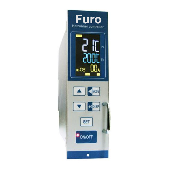
CAUTIONS Please read the instructions carefully before any operation. If there are any signs indicate that the temperature control module is damaged during transportation, please do not power on it. Before the temperature control module is powered on, please 1) Confirm if the power supply of the mainframe meets the requirements;... - Page 5 3. Faceplate ① ON/OFF key: Turn on or turn off the module. *Auto-ON can be selected by parameter “on-”. ② Power indicator: a) Flashing when module is powered up but in off state. b) Light up when module is turned on. ③...
-
Page 6: Operating Modes
4. Operating modes Normal mode: After power on self test, controller starts to work in normal mode. PV displays present temperature value, and SV displays setting temperature value (Auto control) or power output percent (Manual control). Note: Auto/Manual control mode, and the output percent of Manual control when power on, see parameter “nSL”. In this mode, you can <... - Page 7 AT (PID Auto Tune) function: This function is for getting the optimal PID value in some system. It is a “closed-loop” system and requires a thermocouple feedback signal. Generally, AT function is only been executed when PID factory setting cannot meet the system requirements. After finished auto tuning, the optimal PID value would be saved, and the controller returns to normal (auto PID) mode.
- Page 8 9-2. Engineer parameters 1 1) A-n: initial power output percent for manual control, 0~100%, used with parameter nSL. Note: When A-n is effective, its value is auto-refreshed by latest manual output percent. 2) P: control proportional band, 1~999. 3) i: integral time, 0~999s. 4) d: differential time, 0~999s.
- Page 9 9-4. Engineer parameters 3 1) Snb: diagnostic function for misconnection of heater and thermocouple. 0: Off. 1: Checking the heater after power on, if the controller judge it as thermocouple, alarm and cut off output to protect it. : Notes It may cause a false alarm if the heater power is large.
-
Page 10: Alarm Messages
12) on-: status after power-on 0: Off, press ON/OFF key to turn on. 1: Same as the status before power off。 2: Off, press ON/OFF key to turn on; controller auto-changes to manual mode when thermocouple is wrong. 3: Same as the status before power off; controller auto-changes to manual mode when thermocouple is wrong. Note: The manual output percent initial value is 0 (when nSL=0) or equal to parameter “A-n”...
Need help?
Do you have a question about the HRTC-G1 and is the answer not in the manual?
Questions and answers