Table of Contents
Advertisement
Quick Links
Advertisement
Table of Contents

Summary of Contents for Rubix WT1
- Page 1 User Manual RUBIX WT1 WT1 User Manual – Reference N°10002Aen...
- Page 2 Updates INDEX DATE MODIFIED PAGES NOTES (MM/YYYY) 04/2019 All pages Initial Release WT1 User Manual – Reference N°10002Aen 2 /27...
-
Page 3: Table Of Contents
Lumberg Connector for version 3 and newer WT1 devices ............. 24 On/Off signal for version 3 and newer WT1 devices ............... 25 Analog 4-20 mA output signal for version 3 and newer WT1 devices ..........25 On/Off signal for version 2 and older WT1 devices ................. 26 Annex 1 ........................ -
Page 4: Introduction
1 INTRODUCTION This User Manual is intended to help users install and use their WT1 device(s). It has been designed to answer all your questions and advise you in the few minutes that will be necessary to present the device, its features and its functionalities. - Page 5 When using the WT1 system, follow the generally accepted procedure in the field of quality control and method development. It is the user's responsibility to inform RUBIX S & I maintenance personnel before any intervention when the instrument has been used in air containing harmful, toxic, radioactive or biological products.
- Page 6 Do not turn on the instrument if you think it has suffered electrical damage. Instead, unplug the power cord and contact a RUBIX S & I representative for a product evaluation. Do not attempt to use the instrument until it has been evaluated.
-
Page 7: Copyrights
The information contained in this manual may be modified without notice. INSTRUMENT SERIAL NUMBER The serial number is indicated on a label at the bottom of the instrument manufactured by RUBIX S & I. 4 WARRANTY RUBIX S & I warrants this product, parts and labor, for one year from the date of dispatch. -
Page 8: Utilites And Features
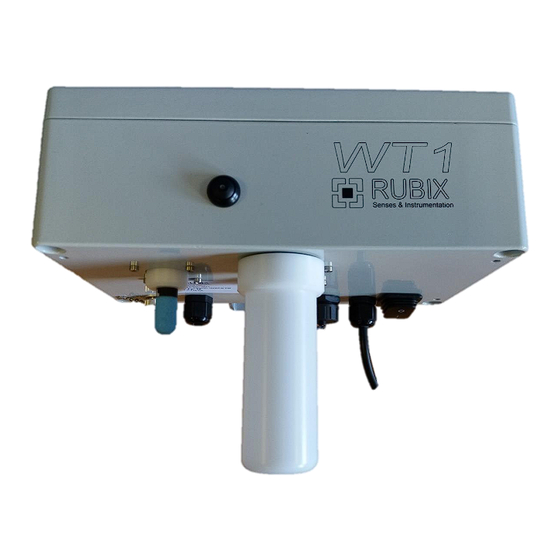
General view of the RUBIX WT1 The RUBIX WT1 is an outdoor device for the monitoring of odours, particules, air pollutants and gases. The instrument is based on a network of sensors : it is equipped with 4 MOS sensors and several electrochemical cells to choose according to the need. -
Page 9: Rubix Wt1 Specifications
- Optional solar version with an autonomous rechargeable battery. RUBIX WT1 diagram and dimensions Note : depending on the version of the WT1, the position of the air outlet, sockets and modules may vary. The 3G/4G key capsule can be longer on newer versions. - Page 10 Figure 3 Figure 4 WT1 User Manual – Reference N°10002Aen 10 /27...
-
Page 11: Assistance
Figure 5 Assistance You can download and print the user guides (PDF) for the RubixSoft® and the POD and WT1 devices at the address www.rubixsi.com. We invite you to contact us for technical support of the application RubixSoft® by email : software@rubixsi.com... -
Page 12: Installation Procedure
There are 4 fixing screws with a maximum diameter of 6 mm. See figures 6 to 8. First screw the fixing piece onto the wall and then mount the WT1 on it (using 4 5mm Allen head screws). WT1 User Manual – Reference N°10002Aen... - Page 13 Figure 6 Figure 7 Figure 8 WT1 User Manual – Reference N°10002Aen 13 /27...
- Page 14 On a « pole » type support : Use flanges of 55 or 60 mm wide and 6mm in diameter with appropriate washers. It is advisable to first install the flanges and the support on the pole and then the WT1 on the support. Figure 9...
-
Page 15: Electrical Supply Of The Device
If you want to install a longer power cable, use an extension cable outside of the unit. 6.3.1 Color code of the power cables Universal color coding : Phase/Line : brown Ground : Green/Yellow Neutral : Blue Figure 13 WT1 User Manual – Reference N°10002Aen 15 /27... -
Page 16: Mains Power Supply
- Input: 100-240 VAC, frequency : 50-60 Hz, 5W - FUSE : 2 AT 6.3.3 Solar power supply The WT1 also exists as a solar powered version if no power outlet is available and the area has sufficient sunlight : Figure 14 Caution : do not power a solar WT1 (12V) using a power outlet (220V) and vice versa. - Page 17 Battery Solar panel Solar panel Figure 16 Finally, install the battery and its charger in the provided protection box : Figure 17 Your system is ready to be used. WT1 User Manual – Reference N°10002Aen 17 /27...
-
Page 18: Starting And Stopping The Device
- When it lights continuously, turn off the unit using the main switch. Communication of the WT1 The WT1 requires an Internet access to communicate the results obtained to the RubixSoft software. Two types of connection are possible : by Ethernet cable (default) or by 3G/4G key. -
Page 19: Use Of The 3G/4G Key
Insert the rubber joint into the cable gland and tighten the CAP as shown in Figure 20. Figure 20 6.5.2 Use of the 3G/4G key If no Ethernet connection is available for WT1 communication with the Rubixsoft software, it is possible to use a SIM card with the supplied 3G/4G key. SIM card specifications •... - Page 20 - Unscrew the 3G/4G key capsule - Remove the 3G/4G key capsule Figure 21 Disconnect the 3G/4G key Figure 22 Open the 3G/4G key Install the SIM card in the key Figure 23 WT1 User Manual – Reference N°10002Aen 20 /27...
-
Page 21: Configuration Update
Install the USB key on the WT1 and switch the device on Wait for the WT1 to initialize Once initialized, you can switch the WT1 off and put the 3G/4G key back on. Switch the device on. The new SIM card should be detected and the device should start to communicate with the RubixSoft (LED blinking once every 10 seconds). -
Page 22: Tedlar Bag Samples
The software update was successfully completed. 7 TEDLAR BAG SAMPLES Installation A Tedlar bag can be connected to the WT1 with an adaptor. All bag sizes are usable. On the bottom of the WT1, locate the air inlet : Air inlet... -
Page 23: Use Of The Tedlar Bag
The Tedlar bag will start to deflate just after it is plugged in. 10 min are required to empty a 10 L bag and it takes 5 min to reach a balance on the WT1. WT1 User Manual – Reference N°10002Aen... -
Page 24: Use Of An External Device
RUBIX S&I is absolutely not responsible for the cable used to connect the 4 pins to an external device WT1 User Manual – Reference N°10002Aen... -
Page 25: On/Off Signal For Version 3 And Newer Wt1 Devices
Pins 3 and 4 are dedicated to the remote control of the sampling box or any other device using a single ON/OFF signal. The ON/OFF signal is provided by the software by programming an alarm. Analog 4-20 mA output signal for version 3 and newer WT1 devices Pin 1 : current loop -... -
Page 26: On/Off Signal For Version 2 And Older Wt1 Devices
7.5 and 40 VDC. (Do not forget that this voltage must be supplied by the user). In the software, the analogue output will be applied to all available parameters of the WT1 (T °, electrochemical sensor, PM, CO2...) and also the parameters of the odor unit (OU). -
Page 27: Annex 1
9 ANNEX 1 APN Examples French Network : Orange operator : gsm.apn = orange gsm.login = orange gsm.password = orange gsm.apn = orange.fr gsm.login = orange gsm.password = orange WT1 User Manual – Reference N°10002A 27 /27...
Need help?
Do you have a question about the WT1 and is the answer not in the manual?
Questions and answers