Advertisement
Quick Links
Advertisement

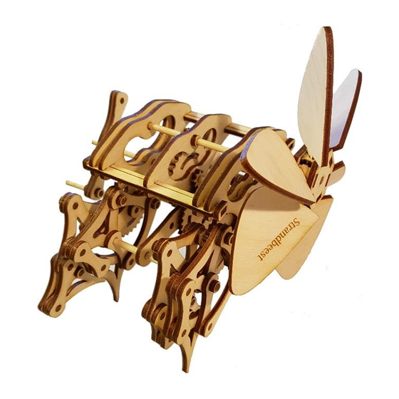
Summary of Contents for Induku Design Strandbeest Kit
- Page 1 Induku Wooden Models Strandbeest Kit Assembly Instructions...
- Page 2 Thank you for shopping at Induku Design. I hope you enjoy building the Strandbeest as much as I did making it! For any questions or comments, please contact me: ronald@indukudesign.com More information about the Strandbeest and electronic copies of this manual available at: www.indukudesign.com...
- Page 3 PVA glue. Wait for the glue to dry completely before continuing with assembly. If the part is not fixable, please contact Induku Design for a replacement. Tip: Work on a hard surface to push parts together to ensure that parts and locks are flush where required.
- Page 4 Assembly instructions: Remove the included Tool 1 (W1 – see part list in back of booklet) from the sheet. Carefully remove all other Tip: Use the thin part of Tool Carefully separate any of the 1 to help separate the dowel pieces that may be model parts from boards narrow parts from the...
- Page 5 D112 (x2); T8 (x2). Place the small gear between the marks on the longest axel (D112) as indicated. Repeat: x2. Important: DO NOT wax any parts with OCTAGON HOLES (e.g. T8). Tight fitting is required for proper function without slippage. D87;...
- Page 6 T32; S1; S4. Place other axel and gear (S1), through the middle hole (S4). Keep in place with large gear T32.The top and middle gear should mesh and move freely. B10; S3; S5. Place other axel and gear (S3), through the bottom hole (S5). Keep in place with B10. Images show the gear train from the front (left) and back (right).
- Page 7 T32 (x4); D5 (x4). Fit the large gear between the lines on axel D5. Tip: Use Tool 2 to hold the small dowels during fitting. Tip: Add a small drop of CA glue to help stop slippage. Ensure this is completely dry before moving on to the next step! B1 (x2);...
- Page 8 B1; B10; S10. Slide another B1 part onto the parts from step 10 as indicated. Keep in place with lock (B10) on bottom axel. B1; B10; S11. Repeat steps 9 and 10 on opposite side. Slide the inner plates outwards to form the main Strandbeest body as shown below. Mesh the two large and one small gear together (do this on each side).
- Page 9 B2 (x2); S11. Add the struts (B2) to the main body, one on each side as indicated. This will fix the side plates in position, and provide rigidity to the structure. Tip: Be patient when fitting the struts – gently work each plate in a bit at a time Important: Ensure that the leg crank orientation does not change during this step.
- Page 10 Leg crank orientation: The orientation of the leg side view cranks are indicated in the image. Note: all cranks on the same plate, face in the same direction. Note: The side view shows all leg cranks at 90 degrees to each other.
- Page 11 D4 (x8); S16. Insert a D4 dowel into the open leg crank holes as indicated. Tip: Use Tool 2 to assist. Important: Support the back of the structure wen pushing dowels in place to ensure that the gear and plates behind the leg crank do not break! round octagon D3 (x16);...
- Page 12 Divide the 8 leg pieces into 2 B10 (x4); D4 (x4); L-C (x4); L-K (x4); S19. groups, i.e. two sets of legs Add part B10 to part D4 and insert into the open hole of part that mirror each other should L2.
-
Page 13: Top View
B10; S17-B; S22. Add the legs to the body as follow: Start with a leg in the B orientation as shown. Place the holes from parts L-J and L-K over each other, and place onto the axel from the leg crank. Keep in place with B10. - Page 14 B10 (x4); S17A; S24. Add legs in the A orientation to the remaining leg crank axels. Keep each leg in place with B10. All 8 legs should be in place on completion of this step. B10 (x4); D96 (x2); S25. Place part B10 on one side of the dowel (D96).
- Page 15 B7 (x6); B8 (x2). Attach parts B7 to B8 as indicated. Place the second part B8 on the opposite side. Important: Pay attention that all the B7 pieces are slanted in the same direction BEFORE the blade hub is completely assembled. B6 (x6);...
- Page 16 Minor improvements: Ensure that all the gears keep running smoothly by adding candle wax. Reduce the chance of slippage by adding a drop of CA glue to where the axel meets the gear. Important: Be carefully not to glue the gears to the body of the Strandbeest. Variations: If the wind is strong enough and the gear train runs...
- Page 17 The Strandbeest leg: The Standbeest was developed by Theo Jansen using an evolutionary algorithm. Using this algorhitm the legs were optimized to have a specific movement pattern. When walking, the Strandbeest seem to have very natural movements, and weight is carried very efficiently. The proportions of the leg segments are very important to generate the movement pattern.
- Page 18 Main structure Struts Strut supports Strut locks plates # 3* # 4* Blades Blade box sides Blade hub Hand crank Locks Small gear Large gear Leg top 8 teeth 32 teeth # 40* # 4* Leg bottom Short, holes Short, holes Long, holes round octagon...
- Page 19 Bent, round and Crank, octagon Tool 1 Tool 2 octagon holes holes Top part # 8* Tool 2 Dowel Dowel Dowel Bottom part 6 mm 9.3 mm 12.6 mm # 3* # 24* # 16* Dowel Dowel Dowel Dowel 16.6 mm 30 mm 87.2 mm 96.2 mm...
- Page 20 Email: Phone: Address: ronald@indukudesign.com +46 070 071 9244 Induku Design c/o Ronald Nelson Website: www.indukudesign.com Fors 105 81591 Shop: www.etsy.com/shop/Induku Tierp Sweden...
Need help?
Do you have a question about the Strandbeest Kit and is the answer not in the manual?
Questions and answers