Advertisement
Quick Install Guide: CLEER24-10G
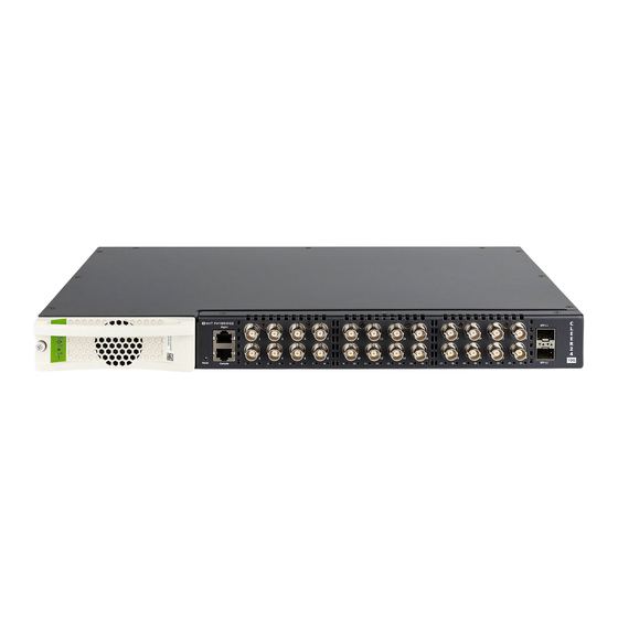
The CLEER24-10G Layer 3 managed switch delivers Fast Ethernet and PoE++ (50
watts per port) over Coax cable with 18 times* the reach of traditional switches.
CLEER was designed to make the migration to IP quick, easy and cost effective
by leveraging an existing Coax infrastructure.
*Using RG6 cable
CLEER24-10G Switch
Installation Details
System Gro unding: See Page 6
Lo catio n and Regio nal Specificatio ns:
The CLEER24-10G can be installed in any indoor location in all
countries except Finland, Norway and Sweden, where, in these 3
Nordic countries, it must be installed in a restricted access location.
CLEER24-10G kan installeras på valfri plats inomhus i samtliga länder
utom Finland, Norge och Sverige; i dessa nordiska länder måste den
installeras på en plats med begränsad åtkomst.
Space Requirements:
1.
Select a standard 19" equipment rack or, for a standalone installation, a flat, stable surface capable of supporting the size and weight of
the CLEER24-10G, its installable components and cabling.
2.
Ensure that you have enough rack space for all equipment. Shelves and rear supporting brackets are not mandatory.
Lo catio n Requirements:
Power - The CLEER24-10G switch must be placed within 6 feet of an available power source. Do not use an extension cord to connect the equipment
to a power outlet.
Ventilation - To ensure proper ventilation of the CLEER24-10G, leave at least 2 inches of unobstructed space on all sides of the unit. If the fans are
blocked, the unit could overheat.
Do wnlink – The adapters should be installed a minimum of 6 feet away from the CLEER24-10G switch.
Installatio n pro cedures will be tro uble‐ free if yo u ensure that the fo llo wing items are available befo re yo u begin:
•
The CLEER24-10G switch, all cables and accessories you received in the CLEER package.
•
SFP/SFP+ transceiver modules for the 10G uplink ports (user-supplied).
•
Fiber or UTP cable (user-supplied) for the SFP/SFP+ modules.
•
Coax cable for the downlink ports (user-supplied).
•
Serial console cable for the CONSOLE port, provided as an accessory in the product package.
•
Standard CAT5e copper LAN cable for the MGMT port (optional). Only needed if out-of-band management is required (user‐supplied).
•
Protective ground cable (user‐supplied).
Hardware Topology and Installation Overview
1.
Remove the CLEER24-10G switch and all accompanying accessories.
2.
Install the rackmount brackets for rack mounting. Unit fits in standard 19" racks.
3.
Install the protective grounding conductor (please refer to the System Grounding section of this guide).
4.
Remove all legacy devices from the cabling. NOTE: It is extremely important that non-IP devices are not connected when you power on the
CLEER24- 10G.
888.901.3633 | +44 (0) 208 977 6614 |
www.nvtphybridge.com
CLEER24-10G kan installeres overalt indendørs undtagen i Finland,
Norge og Sverige, hvor i disse tre nordiske lande den skal installeres
på et sted med begrænset adgang.
CLEER24-10G kan installeres innendørs i alle land unntatt Finland,
Norge og Sverge. I disse tre nordiske landene må den installeres på et
sted med begrenset tilgang.
Copyright 2024 NVT Phybridge | 445-0031-D |
C LE E R 24-Port S witch
C LEER24-10G Packag e Includes:
1 x CLEER24-10G Unit
•
1 x Rackmount Bracket Kit
•
1 x Console Cable
•
1 x Power Cable
•
Page
| 1
Advertisement
Table of Contents

Related Manuals for NVT Phybridge CLEER24-10G


Summary of Contents for NVT Phybridge CLEER24-10G
- Page 1 Power - The CLEER24-10G switch must be placed within 6 feet of an available power source. Do not use an extension cord to connect the equipment to a power outlet. Ventilation - To ensure proper ventilation of the CLEER24-10G, leave at least 2 inches of unobstructed space on all sides of the unit. If the fans are blocked, the unit could overheat.
-
Page 2: Power Capabilities And Considerations
Power Capabilities and Considerations CLEER24-10G switches come standard with a hot swappable PowerWise power supply for power sharing. The switches are amongst the lowest power consuming switches in the industry. For a redundant power configuration, daisy-chain multiple CLEER24-10G switches: You can connect up to a maximum o f 4 units fo r po wer sharing. -
Page 3: Note The Following
Connect the RJ45 end of the serial cable to The following commands must be issued to directly to the console port. the console port of the CLEER24-10G. change VLAN 1's IPv4 address: Connect the serial end of the serial cable to... -
Page 4: Safety Warnings And Precautions
A tápegységet a berendezés közelében kell felszerelni, és könnyen hozzáférhetővé kell tenni • Az ütésveszély vagy a tűzveszély elkerülése érdekében cserélje ki az azonos típusú és minősített biztosítékot 888.901.3633 | +44 (0) 208 977 6614 | www.nvtphybridge.com Copyright 2024 NVT Phybridge | 445-0031-D | Page... - Page 5 Biex ikun evitat ir-riskju ta 'xokk jew perikolu ta' nar, jissostitwixxu fjus bil istess tip u ratifika. ATTENZ JONI: Il lug art huwa terminal prinċipali art li għandha tiġi mqabbda b'mod permanenti mal-art. 888.901.3633 | +44 (0) 208 977 6614 | www.nvtphybridge.com Copyright 2024 NVT Phybridge | 445-0031-D | Page...
-
Page 6: Compliance And Environmental Information
The NVT Phybridge Technical Support Group is available to assist you with product installation, configuration, monitoring and troubleshooting procedures. Should you experience trouble with this equipment or for repair or warranty information, please contact NVT Phybridge Inc. at +1 905.901.3633 or support@nvtphybridge.com. -
Page 7: Technical Specifications
Minimum ambient temperature for cold start-up is 32°F (0°C) MTBF 20 years Specifications subject to change without notice. * No D C power unless supplied by NVT Phybridge power supply units 888.901.3633 | +44 (0) 208 977 6614 | www.nvtphybridge.com Copyright 2024 NVT Phybridge | 445-0031-D |...
Need help?
Do you have a question about the CLEER24-10G and is the answer not in the manual?
Questions and answers