
Summary of Contents for Securiton BRC 535
- Page 1 BRC 535 Beamdetector Remote Control Operating Manual Version 1.0 Securiton AG Alpenstrasse 20 3052 Zollikofen Switzerland T 811 007 a en...
- Page 3 Document history Document history First issue Date 28.04.2010 BRC 535, Operating Manual, T 811 007 en 3 / 24...
-
Page 5: Table Of Contents
Description of the BRC 535 terminal Powering up Presentation of the main menu Battery management General presentation of the BSD 535 – BRC 535 system Introduction Operating mode of the system : Terminal Mode Language on the display BRC 535 terminal connexion... -
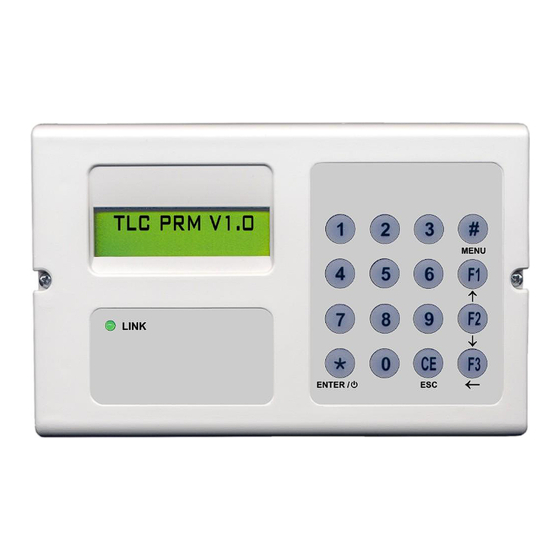
Page 6: Terminal Presentation Brc 535
Terminal presentation BRC 535 The BRC 535 is an aid tool for the installation, start up and maintenance of the SEFI linear smoke detector, version C02 and up. The terminal is also used to set up and test the gas detectors in series DRS900 and GD1XXC and GD1XXA. -
Page 7: Presentation Of The Main Menu
If the charger is connected to the terminal, the connexion is displayed on the screen upon start up. Warning The use of non rechargeable batteries is not allowed with the BRC 535. In all cases, the use of non rechargeable batteries with the BRC 535 linked to the charger may cause an explosion. -
Page 8: General Presentation Of The Bsd 535 - Brc 535 System
General presentation of the BSD 535 – BRC 535 system General presentation of the BSD 535 – BRC 535 system Introduction This section and the following ones describe the operation of the SEFI linear smoke detector version C02 and above with the BRC 535 terminal. -
Page 9: Brc 535 Terminal Connexion
General presentation of the BSD 535 – BRC 535 system BRC 535 terminal connexion The terminal has a wire link. It can be connected : To the detecteur ; To the connection box (BRU 535) In both cases, the terminal connection is done through a cable. -
Page 10: Detector Supply
General presentation of the BSD 535 – BRC 535 system Detector supply The terminal has batteries that allow to supply the BSD 535 when it is not supplied by an ECS. If the detector is already supplied by a loop or a DI line, the terminal does not supply the BSD 535. -
Page 11: Terminal Mode
General presentation of the BSD 535 – BRC 535 system Terminal Mode In this mode, the BSD 535 reports a fault to the central unit. For each of the versions, the (visual indicator) does not show the fault information relating to the switching of the detector into Terminal Mode. -
Page 12: Description Of Scrolling Menus
Menu 1 and Menu 2. Access to MENU 2 is blocked by a password. (password = 1234) Functions of MENU 1 MENU 1 Functions of MENU 2 MENU 2 Main menu diagram 12 / 24 BRC 535, Operating Manual, T 811 007 en... -
Page 13: Menu
MENU 2 Diagram The setting of the DEFNET address only displayed in the DEFNET and CONVENTIONAL versions. The « Relay setting » is only displayed on the RELAY version. BRC 535, Operating Manual, T 811 007 en 13 / 24... -
Page 14: Detailed Function Description
The calibration consists in setting the BSD 535 horizontally and vertically to collect, after reflexion on the reflector, the most in- tense part of the optical pulse released. An accurate setting of the BSD 535 allows to get an optimum signal-to-noise ratio. 14 / 24 BRC 535, Operating Manual, T 811 007 en... - Page 15 Following a proper calibration, it is possible to know the current and gain values recorded by the « detector status information°» function (see D.15). The gain value should be under 200, whatever the conditions and in- stallation distances. Otherwise, resume the BSD 535 calibration. BRC 535, Operating Manual, T 811 007 en 15 / 24...
-
Page 16: Target Test
The standby area The alarm thresholds numbered from 2 to 7 The fault threshold (D). On the second line, for each greyed box there is a level of free space opacity. 16 / 24 BRC 535, Operating Manual, T 811 007 en... -
Page 17: Resetting
The resetting function clears the alarm status of the detector by removing the luminous signal of the IV and of the LED TL. Notice As a reminder when communication is established between the terminal and the BSD 535, it stops any communi- cation with the ECS. BRC 535, Operating Manual, T 811 007 en 17 / 24... -
Page 18: Selection Of Alarm Sensitivity
DAZZLE DELAY: DAZZLE DELAY: PARAMETERS 50 S 50 S CONFIRMED DAZZLE DELAY: PARAMETERS DAZZLE DELAY: 250 S 250 S CONFIRMED DAZZLE DELAY: PARAMETERS DAZZLE DELAY: 900 S 900 S CONFIRMED 18 / 24 BRC 535, Operating Manual, T 811 007 en... -
Page 19: Relay Configuration
That function also allows to indicate the fault condition by the alarm relay. The two possible settings are : Fault on the Fault Relay Fault on the Alarm relay BRC 535, Operating Manual, T 811 007 en 19 / 24... -
Page 20: Setting And Control Of The Defnet Address
When the device is off, the current time is not updated. Once on, the date and time of the device need to be set. Notice The time display is a 0h-24h display 20 / 24 BRC 535, Operating Manual, T 811 007 en... -
Page 21: Display Of Active Setting
FAULTS LIST in chronological order List scrolling CHRONOLOGICAL FULL LIST in chronological order ORDER List scrolling ANTI-CHRONO in anti-chronological order ORDER DELETE DELETION PARAMETERS MEMORY EVENT ? CONFIRMED ? BRC 535, Operating Manual, T 811 007 en 21 / 24... - Page 22 BSD 535 has to have remained on at all times. On the display, when the events are scrolled, the first line is dedicated to the description of the event and the second line to the time and date. 22 / 24 BRC 535, Operating Manual, T 811 007 en...
-
Page 23: Detector State Information
After each pulse, the BSD 535 sends back its condition to the terminal display. 4.15.2.2 Visualisation of measuring parameters This function allows to receive information about : The supply current of the emitting LED The receiving gain BRC 535, Operating Manual, T 811 007 en 23 / 24... -
Page 24: Terminology And Acronyms Used
Visual Indicator of the detector. This indicator has 3 colours : red, orange and green Voltage received at end of the detector’s reception line proportional to the intensity of the luminous im- Vpulse pulse received on the sensor 24 / 24 BRC 535, Operating Manual, T 811 007 en...
Need help?
Do you have a question about the BRC 535 and is the answer not in the manual?
Questions and answers