
Summary of Contents for Milton REX
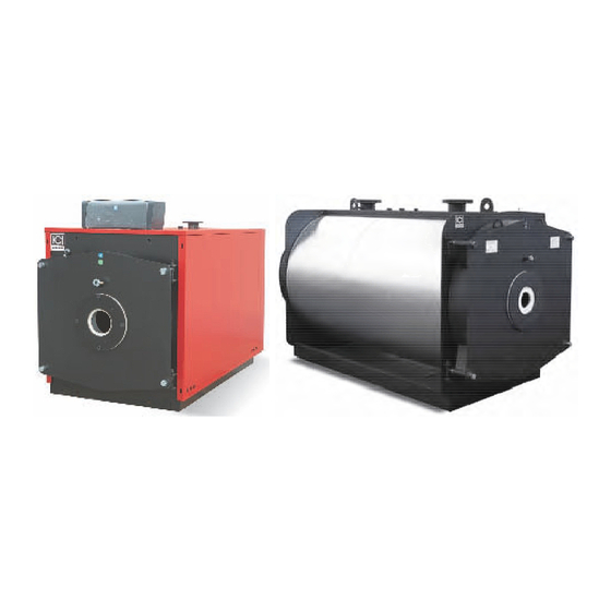
- Page 1 TECHNICAL MANUAL Language: English REX –REX F REX DUAL - REX DUAL F Reverse flame, steel water boiler Output effect: 70-6,000 kW Design pressure: 5, 6, 10, 15 or 16 bar...
- Page 2 ICI-REX Index Index 5.4 Hydraulic connection ....... 23 1 INDEX ............... 1 5.5 Instruments positioning ......25 2 ABOUT THIS MANUAL ........1 5.6 Inverting the manhole opening ....26 5.7 Burner installation ........26 3 GENERAL INFORMATION ......2 5.1 Cabinet assembly ........
- Page 3 ICI-REX General information General information ANUFACTURER PLATE AND CERTIFICATE Each generator is provided with a manufacture plate and a manufacturer certificate. Both can be found in an en- velope together with other boiler documents. On the manufacturer plate the following information is listed: •...
-
Page 4: General Information
Tel. +39 045 8738511 – Fax. +39 045 8731148 info@icicaldaie.com - www.icicaldaie.com ALES AGENT Sole representative for ICI in Scandinavia: Milton Sverige AB Lastgatan 13 • SE-254 64 Helsingborg, Sweden Tel. +46 (0) 4225 2840 – Fax: +46 (0) 4215 8621 info@milton.se –... - Page 5 System filling/drainage Fitting for safety valves Bulb wells Inspection well Figure 1, Dimensions for REX/ REX F size. 7-130 Lastgatan 13 • SE-254 64 Helsingborg Poppelgatan 28 • SE-213 62 Malmø Tel.: +46 (0)4225 2840 • Fax: +46 (0)4215 8621 www.milton.se...
- Page 6 1" 1"1/4 1"1/2 1/2" 1/2" Table 1, Dimensions for REX/ REX F, size 7-130 Notes: Only one safety valve connection for boiler size 40 Lastgatan 13 • SE-254 64 Helsingborg Poppelgatan 28 • SE-213 62 Malmø Tel.: +46 (0)4225 2840 • Fax: +46 (0)4215 8621 www.milton.se...
- Page 7 Technical specifications REX/ REX F size 140-350 Flow Return Fitting for instruments System filling/drainage Fitting for safety valves Bulb wells Inspection well Figure 2, Dimensions for REX/ REX F size 140-350 Øb Øc Boiler size [mm] [mm] [mm] [mm] [mm]...
- Page 8 ICI-REX Technical specifications REX size 400-600 Flow Return Fitting for instruments System filling/drainage Fitting for safety valves Bulb wells Inspection well Figure 3, Dimensions for REX size 400-600 Øb Øc Boiler size [mm] [mm] [mm] [mm] [mm] [mm] [mm] [mm]...
- Page 9 Fitting for safety valves Bulb wells Inspection well Figure 4, Dimensions for REX DUAL / REX DUAL F (vertically stacked), size 14-70 Lastgatan 13 • SE-254 64 Helsingborg Poppelgatan 28 • SE-213 62 Malmø Tel.: +46 (0)4225 2840 • Fax: +46 (0)4215 8621 www.milton.se...
- Page 10 1" 1" 1/2" 1/2" Table 4, Dimensions for REX DUAL / REX DUAL F (vertically stacked), size 14-70 Lastgatan 13 • SE-254 64 Helsingborg Poppelgatan 28 • SE-213 62 Malmø Tel.: +46 (0)4225 2840 • Fax: +46 (0)4215 8621 www.milton.se Tel.: +46 (0)4021 1075 •...
- Page 11 Fitting for safety valves Bulb wells Inspection well Figure 5, Dimensions for REX DUAL / REX DUAL F (vertically stacked), size 80-170 Lastgatan 13 • SE-254 64 Helsingborg Poppelgatan 28 • SE-213 62 Malmø Tel.: +46 (0)4225 2840 • Fax: +46 (0)4215 8621 www.milton.se...
- Page 12 1" 1"1/4 1"1/2 + 1"1/2 1/2" 1/2" Table 5, Dimensioner for REX DUAL / REX DUAL F (vertically stacked), size 80-170 Notes (1) Largest of two fittings (1"1/2) positioned on flow pipe Only one fitting available Lastgatan 13 • SE-254 64 Helsingborg Poppelgatan 28 •...
- Page 13 Fitting for safety valves Bulb wells Inspection well Figure 6, Dimensions for REX DUAL / REX DUAL F (side-by-side), size 80-260 Lastgatan 13 • SE-254 64 Helsingborg Poppelgatan 28 • SE-213 62 Malmø Tel.: +46 (0)4225 2840 • Fax: +46 (0)4215 8621 www.milton.se...
- Page 14 1" 1"1/4 1"1/2 1/2" 1/2" Table 6, Dimensioner for REX DUAL / REX DUAL F (side-by-side), size 80-260 Notes One fitting only Lastgatan 13 • SE-254 64 Helsingborg Poppelgatan 28 • SE-213 62 Malmø Tel.: +46 (0)4225 2840 • Fax: +46 (0)4215 8621 www.milton.se...
- Page 15 2 580 3 264 2 807 91,9 5 147 Table 7, Performance specifications (REX size 7-600) Lastgatan 13 • SE-254 64 Helsingborg Poppelgatan 28 • SE-213 62 Malmø Tel.: +46 (0)4225 2840 • Fax: +46 (0)4215 8621 www.milton.se Tel.: +46 (0)4021 1075 • Fax: +46 (0)4021 4101 Page 14 ICI-REX-EN-v1.03-2011.07.18-HMA...
- Page 16 95,9 193,0 143,0 142,0 2 878 Table 8, Performance specifications (REX F size 7-350) Lastgatan 13 • SE-254 64 Helsingborg Poppelgatan 28 • SE-213 62 Malmø Tel.: +46 (0)4225 2840 • Fax: +46 (0)4215 8621 www.milton.se Tel.: +46 (0)4021 1075 • Fax: +46 (0)4021 4101 Page 15 ICI-REX-EN-v1.03-2011.07.18-HMA...
- Page 17 91,7 75,0 55,7 55,1 1 118 Table 9, Performance specifications (REX DUAL size 14-260) Lastgatan 13 • SE-254 64 Helsingborg Poppelgatan 28 • SE-213 62 Malmø Tel.: +46 (0)4225 2840 • Fax: +46 (0)4215 8621 www.milton.se Tel.: +46 (0)4021 1075 • Fax: +46 (0)4021 4101 Page 16 ICI-REX-EN-v1.03-2011.07.18-HMA...
- Page 18 95,8 71,8 53,3 52,7 1.070 Table 10, Performance specifications (REX DUAL F size 14-260) Notes: (1) @ medium temp. 70 ° C (2) referred to net. calorific value (n.c.v.) (3) acc. to 92/42/EEC (4) G20 refers to methane gas type...
- Page 19 11 330 1/N 230v~ 50 Hz IP 40 Table 11, Specifications for flue gas side, water side, electrical and fuel (REX size 7-600) Lastgatan 13 • SE-254 64 Helsingborg Poppelgatan 28 • SE-213 62 Malmø Tel.: +46 (0)4225 2840 • Fax: +46 (0)4215 8621 www.milton.se...
- Page 20 5 800 1/N 230v~ 50 Hz IP 40 Table 12, Specifications for flue gas side, water side, electrical and fuel (REX F size 7-350) Lastgatan 13 • SE-254 64 Helsingborg Poppelgatan 28 • SE-213 62 Malmø Tel.: +46 (0)4225 2840 • Fax: +46 (0)4215 8621 www.milton.se...
- Page 21 3 686 1/N 230v~ 50 Hz IP 40 Table 13, Specifications for water side, fuel and electrical (REX DUAL size 14-260) Lastgatan 13 • SE-254 64 Helsingborg Poppelgatan 28 • SE-213 62 Malmø Tel.: +46 (0)4225 2840 • Fax: +46 (0)4215 8621 www.milton.se...
- Page 22 2 400 3 686 1/N 230v~ 50 Hz IP40 Table 1, Specifications for water side, fuel and electrical (REX DUAL F size 14-260) Notes: (1) at max. effect and 20 ° C supply air temperatur (2) T = 12 K (3) Inclusive of control panel, excluded pump and burner Lastgatan 13 •...
-
Page 23: Installation
ICI-REX Installation Installation ENERAL Before connecting the boiler, perform the following operations: Thoroughly clean all the system pipes in order to remove any foreign matter that could affect correct • operation of the boiler; Check that the flue has an adequate draught, that there is no narrowing of passages and that it is free •... -
Page 24: Hydraulic Connection
ICI-REX Installation YDRAULIC CONNECTION For hot water heating system with closed expansion vessel and max. 5 or 6 bar pressure, the boiler must be supplied with the following equipment: Furnace output ≤ ≤ ≤ ≤ 300.000 kcal/h Safety valve Expansion vessel (with min. Ø18 mm... - Page 25 ICI-REX Installation Control of hydraulic system before and during startup Ensure that the hydraulic pressure measured after the reduction valve on the supply pipe does not exceed • the operating pressure specified on the rating plate of the boiler (5 or 6 bar for standard boiler type).
- Page 26 ICI-REX Installation NSTRUMENTS POSITIONING REX DUAL / REX DUAL F (side-by-side), size 80-260 Figure 9, Instruments positioning for REX DUAL / REX DUAL F (side-by-side) Pressure switch fitting Flanges to weld after the de- and 2 boiler thermostats finitive and correct positioning...
-
Page 27: Burner Installation
ICI-REX Installation NVERTING THE MANHOLE OPENING The hinging of the boiler front door can be reversed by following this procedure: 1. Switch the outside nut (or bush) of one hinge with the diametrically opposite closure bush; then at the hinge side, fasten the cone to the door with the inside nut. -
Page 28: Cabinet Assembly
Installation ABINET ASSEMBLY Note: The boiler cabinet assembly described in this section applies to REX boiler sizes 7-350 only. For larger boiler sizes no cabinet assembly is required. Assembling of the the case Wrap the fiberglass around the boiler body and use the supplied strap to secure it (see Figure 11). - Page 29 ICI-REX Installation Fasten the uprights and the beams to the plates by means of appropriate screws and nuts. Figure 13, Fastening the uprights NOTE: if the cross beam shown in Figure 14 is supplied in the package it must be placed between the two tube panels in order to support the staves.
- Page 30 ICI-REX Installation Insert the staves, with the previously installed stoppers, between the uprights and the beams, as shown in Figure 15. Figure 15, Inserting the staves NOTE: If the boiler has upper connections it is necessary to install the special central covers, as shown in Figure 16.
- Page 31 ICI-REX Installation Control panel installation On front of boiler A control panel can be installed on the special support supplied in the kit, which must be fastened to the boiler front beam. Pass the cables through the loopholes within the structure (see Figure 17).
-
Page 32: Preliminary Checks
ICI-REX Start up Start up IMPORTANT: Before start up insert all the turbolators into the smoke tubes ensuring that there is a space of at least 100 mm at the front after they have been pushed fully inside. RELIMINARY CHECKS... -
Page 33: Operation
ICI-REX Operation on iron (acid water with Ph < 7): in these cases, although the system is protected from scaling, it is not protected against corrosion and the water must be treated with corrosion inhibitors. ILLING THE SYSTEM The water must enter the system as slowly as possible and in a quantity proportional to the air bleeding capacity of the components involved. - Page 34 ICI-REX Operation Efficiency chart (Significant losses only) Figure 20, Efficiency chart Key: Tf Flue gas temperature [° C] – Ta Ambient temperature [° C] – Go Gas oil – Ho Heavy oil – G Gas Lastgatan 13 • SE-254 64 Helsingborg Poppelgatan 28 •...
- Page 35 ICI-REX Operation EQUIREMENTS FOR WATER TEMPERATURE IMPORTANT: In order to prevent thermal shock to the boiler structure, the differential temperature ( T) between boiler flow and return must not exceed 20 ° C. In order to protect the boiler from corrosion caused by condensation of flue gases, the temperature of the return water must be kept above 55°...
-
Page 36: Maintenance
ICI-REX Maintenance Maintenance LEANING AND SERVICING Always shut off the fuel supply and disconnect the electrical mains before commenc- ing any cleaning and servicing operations. Economic operation depends on clean heat exchange surfaces of the boiler and optimised combustion. The following service operations should be performed regularly: Clean the tube bundle and turbolators (retarders) with the appropriate tube-brush every month for heavy •... - Page 37 ICI-REX CE Certificate Figure 21, CE certificate Lastgatan 13 • SE-254 64 Helsingborg Poppelgatan 28 • SE-213 62 Malmø Tel.: +46 (0)4225 2840 • Fax: +46 (0)4215 8621 www.milton.se Tel.: +46 (0)4021 1075 • Fax: +46 (0)4021 4101 Page 36 ICI-REX-EN-v1.03-2011.07.18-HMA...
Need help?
Do you have a question about the REX and is the answer not in the manual?
Questions and answers