
Summary of Contents for Safe Fleet RVS Air Vue AV-A17
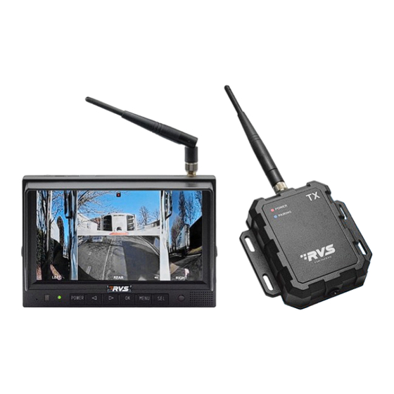
- Page 1 AV-A17 and AV-WT1 Air Vue™ Advanced 2.4GHz Digital Wireless Monitor, Quad View FHD, Touch Screen, Video Output Air Vue™ Wireless Transmitter Instruction Manual © Rear View Safety 2024...
-
Page 2: Table Of Contents
TABLE OF CONTENTS Introduction In The Box Safety Information Precautions 1. Maintenance 2. Features and Specifications 3. Accessories 4. Monitor Parts Identification 5. Menu Operation & Functional Specification 5.1 IR Remote Control 6.System Schematics 7. Air Vue™ Advanced - Multi-Camera Monitor Specification 8. -
Page 3: Introduction
INTRODUCTION Congratulations on purchasing an Air Vue Advanvced Wireless Monitor! With this manual, you can properly install and operate the unit. The wireless monitor is intended to be installed as a supplemental aid to the standard rear- view mirror that already exists in your vehicle. The monitor should not be used as a substitute for your vehicle's standard rear-view mirror or any other mirror. -
Page 4: Safety Information
SAFETY INFORMATION PLEASE READ THE ENTIRE MANUAL AND FOLLOW THE INSTRUCTIONS AND WARNINGS CAREFULLY. FAILURE TO DO SO CAN CAUSE SERIOUS DAMAGE AND/OR INJURY, INCLUDING LOSS OF LIFE. BE SURE TO OBEY ALL APPLICABLE LOCAL TRAFFIC AND MOTOR VEHICLE REGULATIONS AS IT PERTAINS TO THIS PRODUCT. - Page 5 SAFETY INFORMATION INSTALLATION Electric shock or product malfunction may occur if this product is installed incorrectly. • Use this product within the voltage range specified. Failure to do so can cause electronic shock or product malfunction. • Take special care when cleaning the monitor. •...
- Page 6 If you have questions about this product, please contact us at: 800.764.1028 sales@safefleet.net www.rearviewsafety.com New York 1797 Atlantic Ave Brooklyn, NY 11233 Indiana 319 Roske Dr. Elkhart, Indiana 46516 Canada 68 Trafalgar Square Thornhill, ON, L4J 7M5, Canada IN NO EVENT SHALL SELLER OR MANUFACTURER BE LIABLE FOR ANY DIRECT OR CONSEQUENTIAL DAMAGES OF ANY NATURE, OR LOSSES OR EXPENSES RESULTING FROM ANY DEFECTIVE PRODUCT OR THE USE OF ANY PRODUCT.
-
Page 7: Precautions
PRECAUTIONS 1. Do not expose the monitor to excessive heat or coldness. Storage temperature is -30~+80°C; Operating temperature is -20~+70°C; with a maximum relative humidity of 90%. 2. Never use this device near a bathtub, wash basin, kitchen, damp basement, swimming pool or similar places. -
Page 8: Maintenance
1. MAINTENANCE 1. Remove all the cable connections from the monitor before cleaning the device. 2. Use a mild household detergent and clean the unit with a slightly damp, soft cloth. 3. Never use strong solvents such as thinner or benzine, as they might damage the finish of the device. -
Page 9: Features And Specifications
2. FEATURES AND SPECIFICATIONS 1. 7’’ HD quad-view monitor and resolution is 1024 x 600. 2. It supports three wired HD camera inputs + 1 wireless camera input and supports multiple view displays. 3. Multiple video formats available: 1080P30/1080P25/720P30/720P25/PAL/NTSC. 4. Single, dual, triplex, quad, trefoil, Y-split, and PIP view display modes are available. -
Page 10: Accessories
3. ACCESSORIES SPECIAL NOTICE: Accessory supply may be different for different applications. Rear View Safety, 1797 Atlantic Ave., Brooklyn NY 11233 800.764.1028 sales@rearviewsafety.com www.rearviewsafety.com... -
Page 11: Monitor Parts Identification
4. MONITOR PARTS IDENTIFICATION Digital Color LCD Screen Power Indicator Remote Control Menu Sensor Light Sensor Single Split: The screen will be enlarged. Loudspeaker Power Switch Press OK button to switch to split mode. Volume Up Press OK button under Menu to enter Menu options. -
Page 12: Menu Operation & Functional Specification
5. MENU OPERATION & FUNCTIONAL SPECIFICATION 5.1 REMOTE CONTROL Press to select MUTE Enter/exit the standby or enable sound Exit to the main menu or Move up the menu cursor return to the previous menu Move up the menu cursor Move up the menu cur- or increase volume sor or decrease volume... - Page 13 • UP: Switch the channel without auto scan and trigger function turned on; Move the red box in the magnified mode; Move the displayed place of the magnified image. • DOWN: Switch the channel without special mode such as auto scan and trigger function turned on; Move the red box in the magnified mode;...
-
Page 14: System Schematics
6. SYSTEM SCHEMATICS 1. Black: Ground (GND) Air Vue™ 2. Red: Power +12V/+24V - connects to vehicle’s battery Advanced 3. Yellow: * Wireless Transmitter Trailer Circuit *Yellow should be connected to (Wireless 4. White: Trigger 1 - Reverse the same circuit as the wireless Quad View transmitter. -
Page 15: Air Vue™ Advanced - Multi-Camera Monitor Specification
7. AIR VUE™ ADVANCED - MULTI-CAMERA MONITOR SPECIFICATION Features Monitor Specification 3 HD cameras inputs with different resolution (1080P, 720P, PAL, 7” LCD size NTSC). @30 FPS or 25 FPS Resolution 1024 x 3 (RGB) x 600 Supports up to 3 wireless transmitter inputs (shown in single Dot pitch 0.1506(H) ×... -
Page 16: Air Vue™ - Av-Wt1- Transmitter Specification
8. AIR VUE™ - AV-WT1- TRANSMITTER SPECIFICATION Transmitter Specification Power supply DC 10-32V IP69K Water Resistance AHD720P / AHD1080P Video input H.264 Video Compression 2400 - 2483.5 MHz (ISM band) Operation frequency QPSK Modulation 6Mbps RF Bit Rate FHSS Spread spectrum Transmitter Power FCC <... -
Page 17: Rvs-Mv3-Ir-Ahd - Backup Camera Specification
9. RVS-MV3-IR-AHD - BACKUP CAMERA SPECIFICATION Camera Specification Camera Camera PC 3089 Resolution 1080P Lens 2.1mm Lens 170° Viewing Angle Yes - Infra-red Lights Night Vision More than 48dB S/N Ratio IP68 Waterproof Rating Max Frame Rate NTSC: 60 fields/sec, PAL: 50 fields/sec Sync System Internal Synchronization Power Source... -
Page 18: Wiring Instructions When Connecting Power Through Running Lights
10. WIRING INSTRUCTIONS WHEN CONNECTING POWER THROUGH RUNNING LIGHTS • Connect all cameras to their respective monitor connection: Camera 1 will always be the wireless channel. See wiring diagram for recommended camera connections for side and auxiliary cameras. • Wire Connections: On the monitor power harness, the Red wire will be connected to vehicle battery power. -
Page 19: Trailer Camera/Transmitter Cable Routing
11. TRAILER CAMERA/TRANSMITTER CABLE ROUTING Rear View Safety, 1797 Atlantic Ave., Brooklyn NY 11233 800.764.1028 sales@rearviewsafety.com www.rearviewsafety.com... -
Page 20: Transmitter Installation
12. TRANSMITTER INSTALLATION • Identify where you will be making your power connection to the Trailer Running Light Circuit (recommendations on the next page). • Find a suitable location for the Transmitter to be mounted with either screws or nuts and bolts. This can be behind or in front of the sliding axle, depending on power connection location •... -
Page 21: Transmitter Power Connection
13. TRANSMITTER POWER CONNECTION • Using the supplied power harness, connected the Red and Black wires to Trailer light circuit and Ground respectively • Trailer Running Light circuit can be spliced into at the two locations circled above. • Be sure to secure and cover connections so that they do not corrode in the elements •... -
Page 22: Menu Operation
14. MENU OPERATION 14.1 DESKTOP Touch Screen Instructions: • Click the area in the red box as the pic above to open home menu. • Without special mode such as auto scan or trigger function turned on, the swiping to the left and right of the touch screen can switch the display mode following the order: CAM1->CAM2->CAM3- >CAM4->DUAL->TRIPLE->TREFOIL->Y-SPLIT->H.SPLIT->QUAD->PIP1->PIP2->PIP3->SP->CAM1. - Page 23 • Without special mode such as auto scan or trigger function turned on, and when in split view display (not PIP1/2/3 or SP), single touch one of the channel to enter single view display of the channel, and touch again to enter split view. •...
-
Page 24: Home Menu
14.2 HOME MENU Touch Screen Instructions: • Click the icon to enter the corresponding menu. Click the area outside the white box to exit home menu. 14.3 VOLUME (VOL) Touch Screen Instructions: • Touch and drag the volume scroll bar to adjust the volume. •... -
Page 25: Pair
Touch Screen Instructions: • Drag the brightness scroll bar to adjust the brightness. Other Instructions: : Brightness in the day. : Brightness at night. 14.5 PAIR Force the monitor to restart the pairing process with the trailer's wireless transmitter. 14.6 DISPLAY VIEW (TRAILER) Touch Screen Instructions: •... -
Page 26: Sp (Split Setup)
14.6.1 SPLIT SETUP (SP) Touch Screen Instructions: • Click Layer 1-4/Audio icon to switch the page. • When setting up Layer 1-4: click the bottom setting to adjust the position and size of the screen display or whether to turn on this layer. •... -
Page 27: View
14.7 VIEW Touch Screen Instructions: Touch to select preferred image icon and return to previous menu by touching icon 14.8 REC Touch the icon to toggle recording On or Off for the current power cycle. See Record Setting menu to enable or disable recording on every power cycle. 14.9 SYS - MAIN MENU Touch Screen Instructions: •... -
Page 28: Camera
14.9.1 CAMERA Touch Screen Instructions: • Click the camera channel icons on the top to show the parameters of the corresponding channel. • Click the ON/OFF icons or drag the scroll bars to change the features. • Click the icon to edit the camera channel name. -
Page 29: Keyboard (Appears When Editing Camera Name)
14.9.1.1 KEYBOARD (APPEARS WHEN EDITING CAMERA NAME) Touch Screen Instructions: • Click the letter icons to edit the channel name. • Clicking the letter edit box can move the cursor and change the cursor position Remote Instructions: • MODE: Switch the keyboard mode, low-case letters->special numerical character 1->special numerical character 2 ->... -
Page 30: Parking Line
14.9.2 PARKING LINE Touch Screen Instructions: • Click the ON/OFF/AUTO icons to select the display methods of parking lines: AUTO (display when triggered) / ON (constantly on) / OFF. Click the icon to enter parking lines calibration menu “Calibrate”. Remote Instructions: LANG: Switch system language. -
Page 31: Language
• Tapping the icon on the top left will pop up the reset icon and tap it to resume the default config. Tap TYPE1/2 icon on the top right to switch the parking line types. Tap GRID icon to turn on/off the adjustment assistance grids. -
Page 32: Trigger
14.9.4 TRIGGER Touch Screen Instructions: • Touch any of “Delay” line to activate digital input box; Touch any of “Priority” line to activate digital selection box. Touch any of “Display” line to activate interface to select display images. IR Instructions: •... -
Page 33: Input Panel
14.9.4.1 INPUT PANEL Touch Screen Instructions: • Touch the icons to edit the value. Settings will return back to previous menu without saving if touch beyond the panel. Other Instructions: • Input number will turn to 60 if larger than 60. •... -
Page 34: Auto Scan
14.9.5 AUTO SCAN Touch Screen Instructions: • Touch any of “Delay” line to activate digital input box. Touch Enable to turn on/off auto scan function • Touch any of “Display” line to activate interface to select display images. Remote Instructions: •... -
Page 35: Power On
14.9.6 POWER ON The "Power On" function lets you determine what channel combination will appear on monitor screen when monitor powers on. Touch Screen Instructions: • If the icon is not highlighted, touch to highlight it or to cancel its highlight status. Other Instructions: •... -
Page 36: Standard
14.9.7 STANDARD When "Automatic" is on, the monitor will automatically adjust for input cameras. If "Automatic" is off, the monitor will configure with user settings. User is able to set input formats of corresponding cameras via touching icon for each channel or turn on "Automatic" to enter automatic configuration. There will be progressing of automatic configuration, and it will display information of recognized camera after 100% finished. -
Page 37: Channel Video Standard
14.9.7.1 CHANNEL VIDEO STANDARD While using Remote Control or Button Panel, the operation includes 2 selection phases. • Phase 1 Type: If PAL or NTSC is selected, system won’t enter phase 2. • Phase 2 Resolution selection: If user enters this interface from “Standard” menu, it enters phase 1 by default. -
Page 38: Disk
Remote Instructions: • UP / DOWN: Cursor switch. • SEL: Select the camera channel and audio output channel. 14.9.9 DISK The Disk menu allows for viewing and formatting the SD card storage. • Total data storage and amount of available data will be listed on the left side of the display. The green bar will fill up as more storage is utilized. - Page 39 Feature Instructions: • Password: Touch gear icon to setup monitor password protection. Password pop-up will appear when trying to enter settings menu from main screen. • Settings Import/Export: Menu option to import or export all monitor settings to SD card storage. •...
-
Page 40: Auto Dimmer
14.10 AUTO DIMMER Touch Instructions: • Drag scroll bar to adjust backlight of screen in corresponding Day/Night mode. IR Instructions: • LANG: Switch system language. Feature Instructions: • Day: Backlight degree of Day mode is always higher than that of Night mode, ranging from 0 - 60. •... - Page 41 When the monitor initially powers up it will search for a wireless transmitter. The monitor will receive a response from the wireless transmitter over the power line and will begin a hand-shake process to fully pair together. After completion of the hand-shake process, the monitor will display a 'Paired' message indicating that it has successfully connected to the transmitter and will begin communicating wirelessly.
- Page 42 If the monitor and transmitter have successfully paired but the transmitter is not receiving a video image from the camera, a 'No camera image' error will appear on the display. If the hand-shake process has failed and the monitor and transmitter cannot successfully pair, a 'Failed' message will appear on the display.
-
Page 43: Troubleshooting
16. TROUBLESHOOTING Solutions for poor transmitter signal 1. Please confirm the antennas of the display and on the transmitter are perpendicular to the ground, and the antennas are tightened. 2. If there is metal shielding between the monitor and the camera, an extended antenna should be used to bypass the metal shielding to ensure smooth transmission of antenna signal in space. -
Page 44: Warranty
THREE YEAR WARRANTY REAR VIEW SAFETY, INC. WARRANTS THIS PRODUCT AGAINST MATERIAL DEFECTS FOR A PERIOD OF ONE YEAR FROM DATE OF PURCHASE. WE RESERVE THE RIGHT TO REPAIR OR REPLACE ANY SUCH DEFECTIVE UNIT AT OUR SOLE DISCRETION. REAR VIEW SAFETY, INC. IS NOT RESPONSIBLE FOR A DEFECT IN THE SYSTEM AS A RESULT OF MISUSE, IMPROPER INSTALLATION, DAMAGE OR MISHANDLING OF THE ELECTRONIC COMPONENTS. -
Page 45: Disclaimer
DISCLAIMER REAR VIEW SAFETY AND/OR ITS AFFILIATES DOES NOT GUARANTEE OR PROMISE THAT THE USER OF OUR SYSTEMS WILL NOT BE IN/PART OF AN ACCIDENT OR OTHERWISE NOT COLLIDE WITH AN OBJECT AND/OR PERSON. OUR SYSTEMS ARE NOT A SUBSTITUTE FOR CAREFUL AND CAUTIOUS DRIVING OR FOR THE CONSISTENT ADHERENCE TO ALL APPLICABLE TRAFFIC LAWS AND MOTOR VEHICLE SAFETY REGULATIONS. - Page 46 Engineered For Vehicle Safety ™ If you have questions about this product, please contact us at: 800.764.1028 sales@safefleet.net www.rearviewsafety.com New York 1797 Atlantic Ave Brooklyn, NY 11233 Indiana 319 Roske Dr. Elkhart, Indiana 46516 Canada 68 Trafalgar Square Thornhill, ON, L4J 7M5, Canada...
Need help?
Do you have a question about the RVS Air Vue AV-A17 and is the answer not in the manual?
Questions and answers