Table of Contents
Advertisement
Quick Links
Advertisement
Table of Contents

Summary of Contents for Weilekes Elektronik MiniLog2
- Page 1 MiniLog2 Manual...
- Page 2 Weilekes Elektronik GmbH Am Luftschacht 17 45886 Gelsenkirchen Germany Tel: +49 209 170 80-0 Fax: +49 209 170 80-20 www.weilekes.de info@weilekes.de...
-
Page 3: Table Of Contents
MiniLog2 Content Content ................................1 General ................................3 Basics for using the keypad ........................3 Cancel Input ..............................3 Charging Battery ............................3 USB PC Connection............................ 3 GPS Synchronisation ..........................3 Software Reset............................3 LCD Symbols Description ........................... 4 Mode: Switching ............................7 Starting-, Stopping and using Pre Set Cycles..................... - Page 4 MiniLog2 March 2011...
-
Page 5: General
Connect the blue USB cable with the connector "USB Charge" on the bottom of the MiniLog2. The charging can be done via USB mains connector, the USB car adapter or directly via the USB of the PC. The LED named "Charge" lights red during charging, and green when the charging is completed. -
Page 6: Lcd Symbols Description
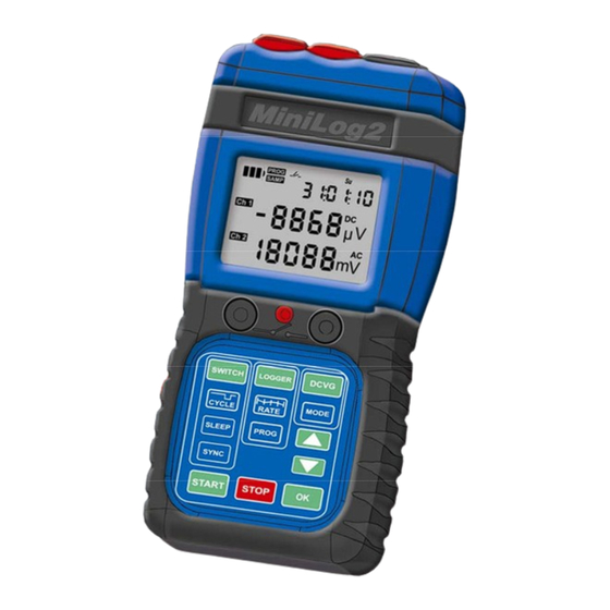
MiniLog2 LCD Symbols Description Battery Capacity Actual Weekday Flashes during charging Small display GPS activated shows time or date GPS signal strength Flashes during reception attempt Flashes during programming Flashes during measuring Relay open / closed Flashes during switching setup... - Page 7 MiniLog2 Mode SWITCH March 2011...
- Page 8 MiniLog2 March 2011...
-
Page 9: Mode: Switching
MiniLog2 Mode: Switching Starting-, Stopping and using Pre Set Cycles The temperature compensated clock of the MiniLog2 allows synchronised switching even when being rarely synchronised. Typical time difference without synchronising is 20ms per day for 10°C to 30°C. Start Switching... -
Page 10: Programming Switching Cycle
MiniLog2 Mode: Switching Programming Switching Cycle Beside the fix preset switching cycles, MiniLog2 allows manual programming of the on and off time. The times can be programmed from 0 to 4s with 0.1s, and above with 1s resolution. Programming SWITCH... -
Page 11: Sleep Mode
MiniLog2 Mode: Switching Sleep Mode With activated sleep mode, the switching will be paused in the night (08:00pm till 07:00am) and during the weekend (Saturday and Sunnday). Activate SWITCH SLEEP Sleeping Mode Choosing Yes / No SLEEP Activate Sleep Mode... -
Page 12: Gps Synchronisation
Mode: Switching GPS Synchronisation If the GPS receiver is connected with the GPS input socket, MiniLog2 automatically tries to synchronise itself every 6 hours with the GPS signal. If a synchronisation at once is required, one can start a GPS synchronisation manually. -
Page 13: External Synchronisation
MiniLog2 Mode: Switch External Synchronisation For the synchronisation of the MiniLog2 with an external switcher, choose the external synchronisation. The external switcher functions as "Master", while the MiniLog2 reacts on the opening of the external contact as a "Slave". The relay contact of the external switcher has to be connected in advance between the channel 1 input and GND. -
Page 14: Manual Synchronisation
Mode: Switch Manual Synchronisation For manual synchronisation of the MiniLog2, choose the manual synchronisation mode. The MiniLog2 will react on pressing the "Start" key, and taking this moment as the start of the off-period of the chosen switching cycle. Selecting Manual... - Page 15 MiniLog2 Mode LOGGER March 2011...
- Page 16 MiniLog2 March 2011...
-
Page 17: Mode: Logger
Mode: Logger Multimeter When used as a multimeter, MiniLog2 measures in fixed range only, without auto ranging. The range has to be changed manually. The input resistance is 10MΩ for range "Hi" (100V) and "Lo" (10V). For the range "Mic"... -
Page 18: Data Logging
2. See also section "Mode Multimeter", "Change Range". For the ranges "Hi" and "Lo" auto range is used during data logging. MiniLog2 will choose the best range automatically for each channel separately. Only if the range "Mic" is pre set, no auto ranging will take place. - Page 19 MiniLog2 Setup channels in the LOGGER multimeter mode Select the displayed channel and its range as described in Mode "Multimeter" in advance for the data logging process. RATE rate shown in top right corner Setup Sampling Rate slower rate faster rate...
- Page 20 MiniLog2 March 2011...
- Page 21 MiniLog2 Mode DCVG March 2011...
- Page 22 MiniLog2 March 2011...
-
Page 23: Mode Dcvg
MiniLog2 Mode DCVG DCVG- or CIPS measurement Electrodes Setup For DCVG measuring, one connects channel 2 (red) and GND (blue) only. For CIPS, the channel 1 takes the test point potential, the channel 2 takes the gradient electrode, and the GND is connected with the electrode above the pipe. - Page 24 MiniLog2 Storing the actual displayed values Stores the on- and off-values of both channels with the keyboard together with the actual GPS coordinates and displays thereafter shortly the amount of already taken measuring points i.e.: POINT If the OK button (accessory of the metal carrying kit) has been connected to the "Feature"...
-
Page 25: Accessories For The Dcvg Survey
MiniLog2 Mode: DCVG Accessories for the DCVG survey Metal carrying kit with "Spring" strap and mounted MiniLog2 GPS- und MinLog2 mounting kit OK button mounted on electrode March 2011... - Page 26 MiniLog2 March 2011...
-
Page 27: Measuring Ranges And Accuracy
MiniLog2 Measuring Ranges and Accuracy DC - Inputs 2 Channels Name Range Resolution Accuracy 100 V > X > 50 V 0,1 V ± 1.0% ± 0.2 V 50 V > X > 0 V 0,01 V ± 0.5% ± 0,02 V 10 V >... -
Page 28: Duration Of Datalogging
MiniLog2 Duration of Datalogging (without / with regards to battery duration ) 4 Channels 2 Channels 1 Channel Sampling Rate (2 x DC, 2 x AC) (1 x DC, 1 x AC) (1 x DC) 300.000 measurements 600.000 measurements 1.200.000 measurements... -
Page 29: Battery Duration
MiniLog2 Battery Duration Mode : Data Logging Sampling Rate Battery Duration 1 ms 100 ms 500 ms 10 d 10 d 15 d 10 s 19 d 30 s 75 d 60 s 150 d Mode : Switching Cycle Mechanic Relay... - Page 30 MiniLog2 March 2011...
-
Page 31: Technical Data
MiniLog2 Technical Data Input Resistance > 10 MΩ (Microvolt 250 KΩ) Filters (only for DC) 16 Hz = 60 dB, 50 Hz = 80 dB, 100 Hz = 100 db Switching Power 15 A 100 VDC / 70 VAC (mechanic) - Page 32 MiniLog2 March 2011...
-
Page 33: Item Numbers
MiniLog2 Item Numbers MiniLog2 with mechanic relay 130111 with electronic relay 130121 complete with USB cable, 230V and 12V USB charger Accessories GPS Receiver 130131 Combined device and accessories bag 130141 for DCVG surveys Metal carrying kit with "Sprint" carrying strap...
Need help?
Do you have a question about the MiniLog2 and is the answer not in the manual?
Questions and answers