
Summary of Contents for NewTechWood K-33
- Page 1 Alusions Parts Product Purpose Part L Bracket K-33 used to fix the Alusions onto the Joist CAF09 Alusions Beam Alusions Beam Installation Guide / v20240112 US...
- Page 2 The table below shows the screws recommended to use for the installation, but not included. Product Purpose Part Used when #8 x 13/16" 1. Fastening the L Bracket (K-33) Stainless Steel onto the Joist. SS401 2. Fixing the Alusions Beam onto (Phillis Recess the joist.
-
Page 3: Installation Procedure
Alusions Beam Horizontal Installation Installation Procedure Step 1: Measure and Chalk the joist Step 2: Fastening the L Bracket (K-33) onto the joist Step 3: Fixing the joist onto the wall or support structure Step 4: Installing the Alusions Beam Two options for the Alusions Beam horizontal installation are recommended, as shown in Diagram A. -
Page 4: Option 1# Installation
The distance underneath the lowest Alusions Beam The Alusions Beam is fastened onto the joist using the to the ground is 11-13/16" (300mm), as shown in L Bracket (K-33), as shown in Detail 1-2. Detail 1-1. Detail 1-1 Detail 1-2... - Page 5 Pre-drill the screw holes on the joist according to the gap distance A plus the length of the long side of the Alusions Beam (CAF09) and the hole position of the L Bracket (K-33), as shown in Detail 2-1. Alusions...
- Page 6 Fasten the L Bracket (K-33) onto the joist with screws, as shown in Detail 2-2, Detail 2-3 and Detail 2-4. Then, fix the joists onto the wall or support structure with screws, as shown in Diagram 2. Detail 2-2 Detail 2-4...
- Page 7 Diagram 3 Pre-drill the screw holes on the Alusions Beam (CAF09) according to the joist span distance and the hole position of the L Bracket (K-33), as shwon in Detail 3-1. Detail 3-1 Alusions Beam Installation Guide / v20240112 US...
- Page 8 Put the Alusions Beam (CAF09) on the L Bracket (K-33) Use screws to fix the Alusions Beam (CAF09) security in place, as shown in Detail 3-2. onto the L Bracket (K-33), as shown in Detail 3-3 and Detail 3-4. Repeat the above procedures to install the remaining Alusions Beams.
- Page 9 The distance underneath the lowest Alusions beam The Alusions Beam is fastened onto the joist using the to the ground is 11-13/16" (300mm), as shown in L Bracket (K-33), as shown in Detail 4-2. Detail 4-1. Detail 4-1 Detail 4-2...
- Page 10 Pre-drill the screw holes on the joist according to the gap distance A plus the length of the short side of the Alusions Beam (CAF09) and the hole position of the L Bracket (K-33), as shown in Detail 5-1. Detail 5-1...
- Page 11 Fasten the L Bracket (K-33) onto the joist with srews, as shown in Detail 5-2, Detail 5-3 and Detail 5-4. Then, fix the joists onto the wall or support structure with screws, as shown in Diagram 5. Detail 5-4 Detail 5-2...
- Page 12 Diagram 6 Pre-drill the screw holes on the Alusions Beam (CAF09) according to the joist span distance and the hole position of the L Bracket (K-33), as shwon in Detail 6-1. Detail 6-1 Alusions Beam Installation Guide / v20240112 US...
- Page 13 Put the Alusions Beam (CAF09) on the L Bracket (K-33) Use screws to fix the Alusions Beam (CAF09) security in place, as shown in Detail 6-2. onto the L Bracket (K-33), as shown in Detail 6-3 and Detail 6-4. Repeat the above procedures to install the remaining Alusions Beams.
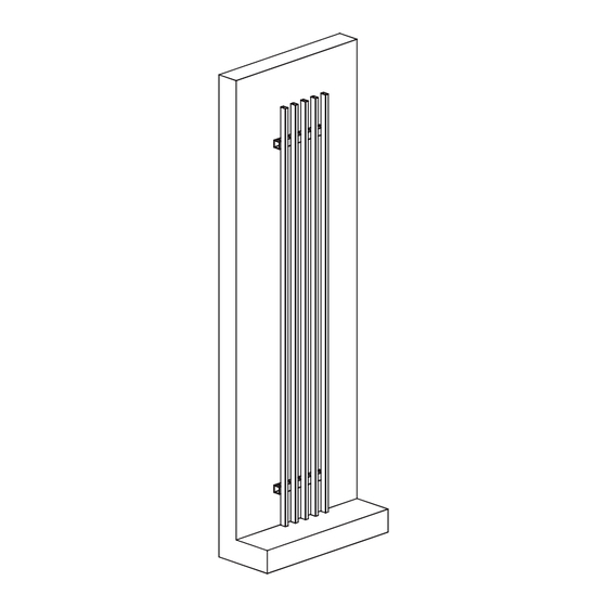
- Page 14 Step 1: Measure and Chalk the Joist Step 2: Fixing the joist onto the wall or support structure Step 3: Fixing the L Bracket (K-33) onto the Alusions Beam (CAF09) Step 4: Installing the Alsions Beam Two options for the Alusions Beam vertical installation are recommended, as shown in Diagram B.
- Page 15 Installation The maximum joist span is 9' 10-1/8" (3m) OC, and the maximum cantilever on both ends is 11-13/16" (300mm), as shown in Diagram 7. Please Note: The installation procedure for the two options is the same. Please carefully read the instructions before the installation.
- Page 16 The distance underneath the Alusions Beam bottom The Alusions Beam is fastened onto the joist using the to the ground is 1-3/16" (30mm) min., as shown in L Bracket (K-33), as shown in Detail 7-2. Detail 7-1. Detail 7-2 Detail 7-1...
- Page 17 Measure and chalk the joist according to the joist span specified, 9' 10-1/8" (3m) max., as shown in Diagram 8. Diagram 8 Alusions Beam Installation Guide / v20240112 US...
- Page 18 The gap distance A plus the length of the long side of the Alusions Beam (CAF09) and the hole position of the L Bracket (K-33), as shown in Detail 8-1. Option 2: The Alusions beam's short side parallels the joist The gap distance A plus the length of the short side of the Alusions Beam (CAF09) and the hole position of the L Bracket (K-33), as shown in Detail 8-2.
- Page 19 Install the Alusions Beam (CAF09) onto the joists, as shown in Diagram 9. Diagram 9 Alusions Beam Installation Guide / v20240112 US...
- Page 20 Pre-drill the screw holes on the Alusions Beam Fix the L Bracket (K-33) onto the Alusions Beam (CAF09) according to the joist span distance, the (CAF09) with screws, as shown in Detail 9-2. cantilever distance, and the L Bracket (K-33) screw holes distance, as shown in Detail 9-1A, Detail 9-1B, and Detail 9-1C.
- Page 21 Use screw to fasten the L Bracket (K-33) that is fixed the Alusions Beam (CAF09) onto the joist , as shown in Detail 9-4 and Detail 9-5. Repeat the above procedures to install the remaining Alusions Beams. Detail 9-4 Detail 9-5...
Need help?
Do you have a question about the K-33 and is the answer not in the manual?
Questions and answers