
Related Manuals for SteelBeast WS-30

Summary of Contents for SteelBeast WS-30
- Page 1 JEI Drilling & Cutting Solutions Ltd OPERATOR’S MANUAL WELD MILLING MACHINE WS-30 Unit 21 Empire Business Park, Enterprise Way, Burnley, BB12 6LT Phone: +44 1706 229490 www.steelbeast.co.uk e-mail: sales@steelbeast.co.uk...
-
Page 2: Table Of Contents
Contents 1. GENERAL INFORMATION ....................3 1.1. Application ......................... 3 1.2. Technical data......................3 1.3. Dimensions ........................ 4 1.4. Equipment included ....................5 1.5. Design ........................6 2. SAFETY PRECAUTIONS ....................7 3. SYMBOLS ......................... 9 4. STARTUP AND OPERATION ..................10 4.1. -
Page 3: General Information
1. GENERAL INFORMATION 1.1. Application The WS-30 WM milling machine is designed for milling the butt welds. It allows for milling welds in depth range from -1.5 mm (-1/16”) to 11 mm (7/16”) at maximum weld width of 30 mm (1 3/16”). -
Page 4: Dimensions
WS-30 WM 1.3. Dimensions 804 mm (31 21/32”) 168 mm (6 39/64”) This document is protected by copyrights. Copying, using, or distributing without permission of JEI Drilling & Cutting Solutions Ltd is prohibited. -
Page 5: Equipment Included
WS-30 WM 1.4. Equipment included Milling machine 1 unit Plastic box 1 unit 1 unit Magnetic guide 1 unit Combination wrench 22 mm Hex wrench 10 mm 1 unit Drift 1 unit Grease 1 unit Cutting inserts 5 units Operator’s Manual 1 unit This document is protected by copyrights. -
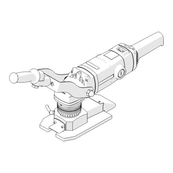
Page 6: Design
WS-30 WM 1.5. Design Switch lock Speed knob Handle Air vents Milling depth knob Chip guard Clamping lever Handle Guide unit Power switch (ON/OFF) Milling head This document is protected by copyrights. Copying, using, or distributing without permission of JEI Drilling & Cutting Solutions Ltd is prohibited. -
Page 7: Safety Precautions
WS-30 WM 2. SAFETY PRECAUTIONS 1. Before use, read this Operator’s Manual and complete a training in occupational health and safety. 2. Use only in applications specified in this Operator’s Manual. 3. Make sure that the machine has all parts and they are genuine and not damaged. - Page 8 WS-30 WM 21. After use, clean the machine and the milling head with a dry cotton cloth and without any chemical agents. Do not remove chips with bare hands. 22. Maintain the machine and attach/remove parts and tool only after you unplug the machine from the power source.
-
Page 9: Symbols
WS-30 WM 3. SYMBOLS Before using the machine, familiarize yourself with the following symbols. Wear eye protection Use hearing protection Read the Operator’s Manual Warning against electric voltage This document is protected by copyrights. Copying, using, or distributing without permission of JEI Drilling & Cutting Solutions Ltd is prohibited. -
Page 10: Startup And Operation
WS-30 WM 4. STARTUP AND OPERATION 4.1. Handle adjustment The milling machine handle may be adjusted in three axes so the operator may adapt it to their needs. To adjust, loosen the domed nuts (1) and screws (2) and (3) using 22 mm flat wrench. -
Page 11: Milling Depth Adjustment
WS-30 WM 4.2. Milling depth adjustment Unplug the power cord. Release the lever (1). Rotate the knob (2) so the scale (3) shows the milling depth “d” (maximum 11 mm (7/16”) and minimum -1,5 mm (-1/16”)). Lock the lever. The depth change is 0.2 mm (1/64″) per graduation or 3 mm (1/8″) per one full turn of the knob. -
Page 12: Cutting Inserts Installation
WS-30 WM 4.3. Cutting inserts installation Unplug the power cord. Position the milling machine with head up. Unlock the lever (1) and rotate knob (2) to disassemble the whole guide unit. CAUTION: do not unscrew the lever (1) completely. It may cause dropping the clamping element. -
Page 13: Replacing The Cutting Inserts
WS-30 WM Prepare screws (1) covered with delivered grease. Put the insert (2) in the socket, press it down and fix with screw, using T15 torx screwdriver. Make sure that the whole bottom of the insert touches the socket. CORRECT ✓... -
Page 14: Turning The Guide Unit
WS-30 WM 4.5. Turning the guide unit Unplug the power cord. Release the lever (1). Hold the milling depth knob (2) so it does not rotate in relation to the guide unit and turn the guide unit to the desired position (3). -
Page 15: Preparation For Machining
WS-30 WM 4.6. Preparation for machining Set the required milling depth. Then use the speed knob to set the rotational speed. Material Rotational speed Setting 3-6 Structural steel of standard quality, quality steel (3100-5850 rpm) The speed knob allows for control of the rotational speed in the range of 1800-5850 rpm. - Page 16 WS-30 WM Start from low milling depth values and increase it gradually. Press the guide unit towards the material surface. Guide the machine in direction indicated by the arrow on the guide unit (1). If an overload occurs, the motor shuts off. This may occur when depth is too large for the hardness of material or when the cutting inserts are dull.
- Page 17 WS-30 WM Position the guide (1) in parallel to the machined weld and in such distance that the head axis is above the weld. Press the milling machine to the guide (2) and start machining in direction indicated by the arrow on the guide unit (3).
-
Page 18: Magnetic Guide
WS-30 WM 4.8. Magnetic guide The milling machine is supplied with the guide allowing for fixing to the ferromagnetic material surface using the magnetic clamps. Fixing method: Loosen the tightening screws (1) and set the clamps in appropriate positions. Retighten the tightening screws. -
Page 19: Head Disassembly
WS-30 WM 4.9. Head disassembly Before disassembly remove chips from the guides. Failure to do so may result in contamination of thread in the guide unit. When it is required to disassemble the guide unit proceed as below. Unplug the power cord. Position the machine in such way that the head is horizontal. - Page 20 WS-30 WM 10 mm This document is protected by copyrights. Copying, using, or distributing without permission of JEI Drilling & Cutting Solutions Ltd is prohibited.
-
Page 21: Replacing The Brushes
WS-30 WM 4.10. Replacing the brushes Every 200 work hours check the condition of the brushes. To do this, unplug the power cord and then remove the cap and the brush. If the brush is shorter than 10 mm (0.4″), replace both brushes with new ones. -
Page 22: Accessories
WS-30 WM 5. ACCESSORIES Magnetic guide Part number: PRW-0761-99-00-00-0 This document is protected by copyrights. Copying, using, or distributing without permission of JEI Drilling & Cutting Solutions Ltd is prohibited. -
Page 23: Declaration Of Conformity
UNIT 21 EMPIRE BUSINESS PARK ENTERPRISE WAY, BURNLEY LANCASHIRE, BB12 6LT We declare with full responsibility that: Weld milling machine WS-30 WM is manufactured in accordance with the following standards: • EN ISO 12100: 2010 • EN 62841-1: 2015 • EN 55014-1: 2017 and satisfies the regulations of the guidelines: 2014/30/EU, 2006/42/EC, 2011/65/EU. -
Page 24: Environmental Protection
WS-30 WM 7. ENVIRONMENTAL PROTECTION In accordance with the European Directive 2012/19/EU, this device is marked with the symbol of the crossed-out waste bin. This marking means that the equipment must not be disposed of with other household waste after the service life. The user must return the product to a collection point for used electrical and electronic equipment. -
Page 25: Warranty Card
WS-30 WM 8. WARRANTY CARD WARRANTY CARD No..... ……………………….. in the name of Manufacturer warrants the BM-30 WM milling machine to be free of defects in material and workmanship under normal use for a period of 12 months from the date of sale.
Need help?
Do you have a question about the WS-30 and is the answer not in the manual?
Questions and answers