
Related Manuals for ADLINK Technology LPCIe-3488A

Summary of Contents for ADLINK Technology LPCIe-3488A
- Page 1 LPCIe/LPCI/USB-3488A IEEE488 GPIB Interface Card Series User’s Manual Manual Rev.: Revision Date: March 13, 2023 Part No: 50M-00129-1040...
- Page 2 Revision History Revision Release Date Description of Change(s) 2009-10-13 Initial release 2014-12-12 LPCIe version added 2023-03-13 LPCIe, USB PCB revisions...
-
Page 3: Preface
LPCIe/LPCI/USB-3488A Preface Copyright 2009, 2014, 2023 ADLINK Technology, Inc. This document contains proprietary information protected by copy- right. All rights are reserved. No part of this manual may be repro- duced by any mechanical, electronic, or other means in any form without prior written permission of the manufacturer. - Page 4 Conventions Take note of the following conventions used throughout this manual to make sure that users perform certain tasks and instructions properly. Additional information, aids, and tips that help users perform tasks. NOTE: NOTE: Information to prevent minor physical injury, component dam- age, data loss, and/or program corruption when trying to com- plete a task.
-
Page 5: Table Of Contents
Certifications ..............3 General Specifications ............ 3 Software Support ..............4 2 Installation ................5 Package Contents ............... 5 LPCIe/LPCI-3488A ............5 USB-3488A ..............5 Unpacking................6 Mechanical Drawings............7 LPCI-3488A ..............7 LPCIe-3488A ..............8 USB-3488A ..............9 Table of Contents... - Page 6 PCI/PCIe Configuration............10 Plug and Play ..............10 Configuration ..............10 Troubleshooting ............10 Hardware Installation ............11 LPCIe/LPCI-3488A Installation Procedures ....11 USB-3488A Installation Procedures ......11 Cabling ................12 Software Installation............15 Driver Installation ............16 Using the ADLINK GPIB Utility ........17 3 Operations ................
-
Page 7: List Of Tables
LPCIe/LPCI/USB-3488A List of Tables Table 3-1: GPIB Bus Pin Definitions ..........22 List of Tables... - Page 8 This page intentionally left blank. viii List of Tables...
-
Page 9: List Of Figures
LPCIe/LPCI/USB-3488A List of Figures Figure 2-1: PCB Layout of the LPCI-3488A ........7 Figure 2-2: PCB Layout of the LPCIe-3488A ........8 Figure 2-3: Layout of the USB-3488A ..........9 Figure 2-4: LPCIe/LPCI-3488A Linear Connection Configuration..12 Figure 2-5: USB-3488A Linear Connection Configuration ....13 Figure 2-6: LPCIe/LPCI-3488A Star Connection Configuration .. - Page 10 This page intentionally left blank. List of Figures...
-
Page 11: Introduction
LPCIe/LPCI/USB-3488A Introduction 1.1 Overview ADLINK’s LPCIe/LPCI/USB-3488A GPIB controller interface cards are fully compatible with the IEEE488.2 instrumentation control and communication standard and are capable of controlling up to stand-alone instruments IEEE488 cables. LPCIe/LPCI/USB-3488A are designed to meet the requirements for high performance and maximum programming portability. They were developed using ADLINK’s intellectual property in FPGAs which incorporates the GPIB controller, provides reliable GPIB bus control capability, and supports a transfer rate up to 1.5 MB/s. -
Page 12: Features
LPCIe/LPCI-3488A The LPCIe/LPCI-3488A IEEE 488 GPIB interface card provides the following advanced features: PCI Express 1.1 compatibility (LPCIe-3488A) Supports 32-bit 3.3 V or 5 V PCI bus (LPCI-3488A) Fully compatible with IEEE 488.1 and 488.2 standard Up to 1.2 MB/s data transfer 2 kB onboard FIFO for read/write operations APIs provided compatible with NI-488.2 driver software... -
Page 13: Specifications
Storage temperature: -20 to 80ºC at 10 to 90% humidity Relative humidity: 10 to 90%, non-condensing Power requirements LPCI-3488A +5 V 250 mA (typical) 300 mA (max.) LPCIe-3488A +3.3V +12V 90 mA (max.) 150 mA (max.) 80 mA (typ.) 100 mA (typ.) -
Page 14: Software Support
190 mA (typical) 500 mA (maximum) Dimensions (not including connectors): LPCI-3488A: 120 (L) x 64 (H) mm LPCIe-3488A: 119.7 (L) x 68.9 (H) mm USB-3488A : 81.6 (L) x 61.5 (W) x 27.8 (H) mm Vibration Test USB-3488A Operating: 1 G 3 axes non-operating: 2.5 G 3 axes... -
Page 15: Installation
LPCIe/LPCI/USB-3488A Installation This chapter outlines the contents of package, describes unpack- ing information, and describes how to install the hardware and software. 2.1 Package Contents LPCIe/LPCI-3488A The LPCIe/LPCI-3488A includes the following items: LPCIe/LPCI-3488A USB-3488A The USB-3488A includes the following items: USB-3488A with built-in 2m cable If any of these items are missing or damaged, contact your ADLINK dealer. -
Page 16: Unpacking
2.2 Unpacking The LPCIe/LPCI/USB-3488A modules contain electrostatically sensitive components that can be easily be damaged by static electricity. Therefore, they should be handled on a grounded anti-static mat. The operator should be wearing an anti-static wristband, grounded at the same point as the anti-static mat. Inspect the module for obvious damage. -
Page 17: Mechanical Drawings
LPCIe/LPCI/USB-3488A 2.3 Mechanical Drawings LPCI-3488A Figure 2-1: PCB Layout of the LPCI-3488A Installation... -
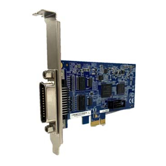
Page 18: Lpcie-3488A
LPCIe-3488A Figure 2-2: PCB Layout of the LPCIe-3488A Installation... -
Page 19: Usb-3488A
LPCIe/LPCI/USB-3488A USB-3488A 64.50 Figure 2-3: Layout of the USB-3488A The USB-3488A GPIB interface provides a direct connection between the USB port on a desktop or laptop computer to GPIB instrument. With the USB-3488A GPIB interface and its USB Plug and Play feature, GPIB instruments can be connected and discon- nected without having to shut down the computer. -
Page 20: Pci/Pcie Configuration
2.4 PCI/PCIe Configuration Plug and Play As a plug-and-play component, the card requests an interrupt number via its PCI/PCIe controller. The system BIOS responds with an interrupt assignment based on the card information and on known system parameters. These system parameters are deter- mined by the installed drivers and the hardware is acknowledged by the system. -
Page 21: Hardware Installation
3. Open the computer case. 4. For LPCI-3488A, select a 32-bit PCI slot. For LPCIe-3488A, select a PCIe x1 slot. 5. Before handling the PCI/PCIe cards, discharge any static buildup on your body by touching the metal case of the computer. -
Page 22: Cabling
Cabling The following connection configuration can ensure that the GPIB throughput achieves optimal performance. These configurations include the number of instruments and cable distances: Cable lengths should be no longer than 4 meters (2 meter lengths maximum is suggested). The total GPIB BUS distance should be less than 20 meters. -
Page 23: Figure 2-5: Usb-3488A Linear Connection Configuration
LPCIe/LPCI/USB-3488A Figure 2-5: USB-3488A Linear Connection Configuration Figure 2-6: LPCIe/LPCI-3488A Star Connection Configuration Installation... -
Page 24: Figure 2-7: Usb-3488A Star Connection Configuration
Figure 2-7: USB-3488A Star Connection Configuration For a star connection, the total current load will be less in the presence of fewer than three cable connections on an individ- ual instrument. NOTE: NOTE: Installation... -
Page 25: Software Installation
LPCIe/LPCI/USB-3488A 2.6 Software Installation ADLINK GPIB interface cards are equipped with an ADL-GPIB driver package for Windows XP/7/8/10/11. The ADL-GPIB is designed to be fully compatible with your current applications and includes APIs and a binary-compatible gpib-32.dll for users using LabVIEW, VC++, VB, and Delphi. -
Page 26: Driver Installation
Driver Installation 1. Download ADL-GPIB.exe from Adlink website. 2. Execute ADL-GPIB.exe to launch the setup program. 3. Reboot the system to complete setup Installation... -
Page 27: Using The Adlink Gpib Utility
LPCIe/LPCI/USB-3488A Using the ADLINK GPIB Utility The ADL-GPIB driver package also provides the ADLINK GPIB Utility to diagnose and verify GPIB connections, located at x:\ADLINK\ADL-GPIB\Utility\GPIB Utility.exe NOTE: NOTE: 1. Launch GPIB Utility.exe. A window appears showing all installed GPIB interfaces and instruments Installation... - Page 28 2. Click on a GPIB interface (GPIB0, GPIB1, etc.) and select “Setting” > “GPIB Preference”. A “GPIB Interface & Bus Setting” dialog appears to enable configuration of the GPIB interface. Installation...
- Page 29 LPCIe/LPCI/USB-3488A 3. Double click on a connected GPIB instrument. A ‘”GPIB Interactive control” dialog appears to allow write com- mand strings to be inputted into the GPIB instrument and read the result. Installation...
- Page 30 This page intentionally left blank. Installation...
-
Page 31: Operations
LPCIe/LPCI/USB-3488A Operations This chapter describes the operation theory of GPIB bus and the basic architecture of ADLINK’s GPIB interface cards. 3.1 Connection Configuration The GPIB bus has 24 lines which are divided into 16 signal lines and 8 ground return or shield drain lines. The 16 signal lines can be divided into 8-bit parallel data transfer bus and 8 control lines. - Page 32 GPIB Type Function Descriptio DIO1 DIO2 DIO3 8 data lines DIO4 DIO5 DIO6 DIO7 16 signal lines DIO8 5 system management lines 24 lines 8 control lines 3 handshake lines NRFD NDAC 1 shield drain line SHIELD 8 ground lines 7 ground return lines SIGNAL GROUND...
-
Page 33: Data Lines
LPCIe/LPCI/USB-3488A Data Lines DIO1 to DIO8 carry both data and command messages. All com- mands and most data use 7-bit ASCII codes, the 8th bit, DIO8, is either unused or used as a parity check. Handshake Lines Three handshake lines control the transfer of data/messages between devices. -
Page 34: Block Diagrams
3.2 Block Diagrams ADLINK GPIB Interface Cards The ADLINK LPCIe-3488A FPGA includes a 2kB FIFO to maxi- mize data transfer rate, coordinating data flow between the PCIe bus, FIFO and GPIB bus. FPGA PCIe x1 Interface Transceiver/ GPIB IP 2K FIFO... -
Page 35: Figure 3-4: Usb-3488A Block Diagram
LPCIe/LPCI/USB-3488A The ADLINK USB-3488A GPIB interface include a 32 KB FIFO to maximize data transfer rates. Its state-of-the-art state machine in the 8051 coordinates the data flow between the USB Bus, FIFO and GPIB bus. FPGA Transceiver/ 8051 GPIB IP Receiver SRAM Figure 3-4: USB-3488A Block Diagram... - Page 36 This page intentionally left blank. Operations...
-
Page 37: Important Safety Instructions
LPCIe/LPCI/USB-3488A Important Safety Instructions For user safety, please read and follow all instructions, WARNINGS, CAUTIONS, and NOTES marked in this manual and on the associated equipment before handling/operating the equipment. Read these safety instructions carefully. Keep this user’s manual for future reference. Read the specifications section of this manual for detailed information on the operating environment of this equipment. - Page 38 Never attempt to fix the equipment. Equipment should only be serviced by qualified personnel. A Lithium-type battery may be provided for uninterrupted, backup or emergency power. RISK OF EXPLOSION IF BATTERY IS REPLACED BY AN INCORECT TYPE. DISPOSE OF USED BATTERIES ACCORDING TO THEIR INSTRUCTIONS.
-
Page 39: Getting Service
6450 Via Del Oro, San Jose, CA 95119-1208, USA Tel: +1-408-360-0200 Toll Free: +1-800-966-5200 (USA only) Fax: +1-408-600-1189 Email: info@adlinktech.com ADLINK Technology (China) Co., Ltd. 300 Fang Chun Rd., Zhangjiang Hi-Tech Park Pudong New Area, Shanghai, 201203 China Tel: +86-21-5132-8988 Fax: +86-21-5132-3588 Email: market@adlinktech.com ADLINK Technology GmbH Hans-Thoma-Straße 11...
Need help?
Do you have a question about the LPCIe-3488A and is the answer not in the manual?
Questions and answers