Sign In
Upload
Download
Add to my manuals
Delete from my manuals
Share
URL of this page:
HTML Link:
Bookmark this page
Add
Manual will be automatically added to "My Manuals"
Print this page
×
Bookmark added
×
Added to my manuals
Manuals
Brands
NCR Manuals
Security Camera
FastLane SelfServ Checkout 7357
Instructions manual
NCR 7357 Instructions Manual
Ip camera field upgrade (d-vitec)
Hide thumbs
Also See for 7357
:
Kit instructions
(6 pages)
1
2
3
4
5
6
7
8
9
10
11
12
13
14
15
16
17
18
19
20
21
22
23
24
25
26
27
28
29
30
31
32
33
34
35
36
37
38
39
40
41
42
43
44
45
46
47
48
49
50
51
52
53
54
55
56
page
of
56
Go
/
56
Bookmarks
Advertisement
Quick Links
Download this manual
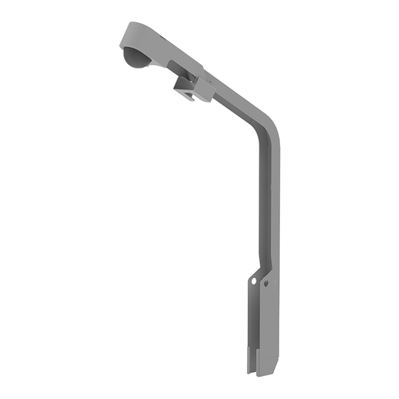
Kit Instructions
IP Camera Field Upgrade (D-Vitec)
7360-K089
Issue A
Confidential and proprietary information of NCR Voyix Corporation.
Unauthorized use, reproduction and/or distribution is strictly prohibited
Table of
Contents
Previous
Page
Next
Page
1
2
3
4
5
Advertisement
Need help?
Do you have a question about the 7357 and is the answer not in the manual?
Ask a question
Questions and answers
Related Manuals for NCR 7357
Racks & Stands NCR SelfServ Checkout 7350 Kit Instructions
(6 pages)
Payment Terminal NCR FastLane SelfServ Checkout 7358 Kit Instructions
Non-scale 2-bag bagwell upgrade (37 pages)
Security Camera NCR 7360 Instructions Manual
Ip camera field upgrade (d-vitec) (56 pages)
This manual is also suitable for:
7358
7360
Print
Rename the bookmark
Delete bookmark?
Delete from my manuals?
Login
Sign In
OR
Sign in with Facebook
Sign in with Google
Upload manual
Upload from disk
Upload from URL


Need help?
Do you have a question about the 7357 and is the answer not in the manual?
Questions and answers