Table of Contents
Advertisement
Quick Links
REV.
Description
REV.
首次发行
00
余雅萍
2023/06/02
描述
说明书 一拖二微逆系列 英文版 SolaX
浙江艾罗网络能源技术股份有限公司
料号
SolaX Power Network Technology
320101069600
(Zhejiang) Co., Ltd.
单位
页次
mm
Description
技术要求:
1. 封面封底 157g 铜版纸覆哑膜彩打,内部纸 80g 双胶纸黑白印刷,正反打印;
2. 装订方式:胶装或骑马钉,内页大于 60 页时须胶装;
3. 未注尺寸公差按 ±3 mm;
4. 图面、字体印刷清晰、无偏移、无毛边、不起边、油墨不脱落;
5. 黑色字体颜色为 PANTONE BLACK C, 无边框,底色为白色;
6. 符合 ROHS 要求。
143 mm
X1-Microinverter 2-in-1
800 W / 900 W / 1000 W / 1200 W
User Manual
Version 0.0
www.solaxpower.com
eManual in the QR code or at
http://kb.solaxpower.com/
描述
说明书 一拖二微逆系列 英文版 SolaX
材料
双胶纸
料号
320101069600
单位
页次
mm
设计
余雅萍 2023/06/02
审核
周卓建 2023/06/02
核准
施鑫淼 2023/06/02
浙江艾罗网络能源技术股份有限公司
Advertisement
Table of Contents

Summary of Contents for Technea SolaX Power X1-Microinverter 2-in-1
- Page 1 REV. Description REV. Description 首次发行 143 mm 余雅萍 2023/06/02 X1-Microinverter 2-in-1 800 W / 900 W / 1000 W / 1200 W User Manual Version 0.0 www.solaxpower.com eManual in the QR code or at http://kb.solaxpower.com/ 技术要求: 1. 封面封底 157g 铜版纸覆哑膜彩打,内部纸 80g 双胶纸黑白印刷,正反打印; 2.
- Page 2 X1-Microinverter 2-in-1 800 W / 900 W / 1000 W / 1200 W User Manual Version 0.0 www.solaxpower.com eManual in the QR code or at http://kb.solaxpower.com/...
- Page 3 STATEMENT Copyright Copyright © SolaX Power Technology (Zhejiang) Co., Ltd. All rights reserved. No part of this manual may be reproduced, transmitted, transcribed, stored in a retrieval system, or translated into any language or computer language, in any form or by any means without the prior written permission of SolaX Power Technology (Zhejiang) Co., Ltd.
- Page 4 About This Manual Scope of Validity This manual is an integral part of X1-Microinverter 2-in-1 Series. It describes the installation, electrical connection, commissioning, maintenance and troubleshooting of the product. Please read it carefully before operating. X1-Micro 800 X1-Micro 900 X1-Micro 1000 X1-Micro 1200 Note: "X1-Microinverter"...
- Page 5 Conventions The symbols that may be found in this manual are defined as follows. Symbol Description Indicates a hazardous situation which, if not avoided, DANGER will result in death or serious injury. Indicates a hazardous situation which, if not avoided, WARNING could result in death or serious injury.
-
Page 6: Table Of Contents
Table of Contents Safety ......................1 1.1 General Safety ........................1 1.2 Safety Instructions of PV, Microinverter and Grid ............1 1.2.1 Safety Instructions of PV ..................2 1.2.2 Safety Instructions of Microinverter ..............2 1.3 Safety Instructions of Utility Grid ..................4 1.3.1 Safety Instructions of AC cable ................4 1.4 Microinverter System Description .................5 1.5 Highlights ..........................7 1.6 Appearance .........................8... - Page 7 4.3 On-Site Inspection (for qualified installaer only) ............32 4.4 Maintenance ........................32 4.4.1 Maintenance routines ..................33 4.4.2 Upgrading Firmware ....................33 4.5 Microinverter Replacement ....................35 Decommissioning ..................37 5.1 Disassembling the Microinverter .................37 5.2 Packing the Microinverter ....................37 5.3 Transportation and Storage ....................37 5.4 Disposal of the Microinverter ..................38 Technical Data ..................39 Appendix ....................41...
-
Page 8: Safety
Safety General Safety This series of microinverter is well designed and tested to meet all applicable states and international safety standards. However, like all electrical and electronic equipment, safety precautions must be observed and followed during the installation of the microinverter to reduce the risk of personal injury and to ensure a safe installation. -
Page 9: Safety Instructions Of Pv
Safety 1.2.1 Safety Instructions of PV DANGER! Lethal danger from electric shock due to the PV! • Never touch the positive or negative pole of PV connecting device. Touching both of them at the same time is prohibited as well. •... - Page 10 Safety WARNING! • The installation place should be away from humid or corrosive substance. Avoid installation near extremely hot/cold environment. • Please consult the manufacutuer for non-standard installation conditions. • Make sure that the microinverter is installed under the PV module in case of direct exposure to UV, rain and other harmful weather events.
-
Page 11: Safety Instructions Of Utility Grid
Safety Safety Instructions of Utility Grid NOTICE! • Only with permissions of local utility grid company, the microinverter can be connected to the grid. • The installer must provide Over Current Protection Devices (OCPD) and external disconnect switches. 1.3.1 Safety Instructions of AC cable DANGER! •... -
Page 12: Microinverter System Description
Safety Product Overview Microinverter System Description A microinverter system is composed of PV grid-connnected microinverters, PV modules, and grid. Microinverter data are transmitted to SolaX monitoring platform SolaXCloud. Figure 1-1 System overview diagram X1-Microinverter 2-in-1 series The X1-Microinverter 2-in-1 series manages system energy. Microinverters convert the direct current power generated from the PV modules into grid- compatible AC current. - Page 13 The X1-Microinverter 2-in-1 is integrated with MPPT, which means that even though a PV module runs abnormally or is shaded, other modules won't be affected and can operate the unshaded string at maximum efficiency point. This function plays an important role to improve the efficiency of a photovoltaic (PV) generation system.
-
Page 14: Highlights
Safety Highlights • Module-level monitoring on the data of module voltage, current, internal temperature, and meter value without monitoring host • Build-in Wi-Fi communication module, independently accessing to Internet • Up to 20 A DC input current to be compatible with the high power PV module •... -
Page 15: Appearance
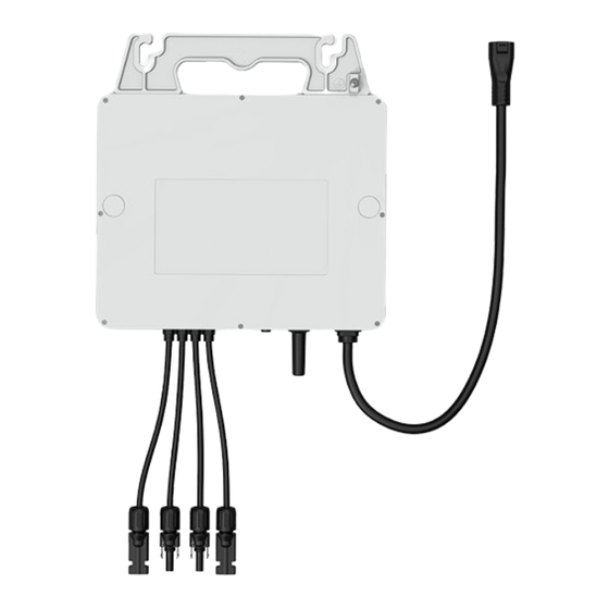
Safety Appearance 1.6.1 Overview Figure 1-2 Apprearance Table 1-1 Desciption of appearance 1.6.2 Dimensions 260 mm 40 mm Figure 1-3 Dimensions 1.6.3 Terminals of Microinverter... -
Page 16: Symbols On The Label And Microinverter
Safety Figure 1-4 Terminals of Microinverter Table 1-2 Description of terminals Item Description Spare ground For standby earth connection. cable clip PV cable port For PV connection. Indicator Show the status of the device. Antenna To receive and transmit WiFi signal. AC cable port For AC connection. - Page 17 Safety Symbol Description Danger of high voltages. Danger to life due to high voltages in the Microinverter ! Danger. Risk of electric shock! Danger to life due to high voltage. There is residual voltage in the inverter which needs 5 min to discharge.
-
Page 18: Preparation Before Installation
Preparation before Installation Preparation before Installation Unpacking and Inspection 2.1.1 Unpacking • The microinverter undergoes 100% testing and inspection before shipping from the manufacturing facility. However, transport damage may still occur. Before unpacking the Microinverter , please verify that the model and outer packing materials for damage, such as holes and cracks. -
Page 19: Packing Lists
Preparation before Installation Packing Lists Microinverter Installation Map Make sure N for North Panel type: Customer information: Gateway series number: Azimuth: Tilt: Sheet_of_ COLUMN A: Documents B: Installation map Inverter Sold separately: AC trunk port disconnect 1.2m/2m/2.4m AC trunk AC trunk end cap AC trunk connector tool cable... -
Page 20: Installation Angel Requirement
Preparation before Installation • Install all microinverters and DC connectors under the PV modules. • Avoid direct exposure to UV, rain and other harmful weather events. • Avoid electromagnetic interference in case of the malfunction of electronic equipment. -40°C-+65°C IP67 0-100%RH No direct sunlight No rain exposure... -
Page 21: Recommended Equipment
Preparation before Installation 2.4.1 Recommended Equipment Installation tools include but are not limited to the following recommended ones. If necessary, use other auxiliary tools on site. Cable tie Multimeter Measuring tape Utility knife Marker Cross screwdriver Diagonal pliers Allen key Wire cutter Wire stripper Safety gloves... - Page 22 Preparation before Installation Maximum over X1-Microinverter X1-Microinverter current protection device 11@220V 9@220V Maximum number 11@230V 10@230V 40 A per 10AWG branch 12@240V 10@240V Maximum over X1-Microinverter X1-Microinverter current protection 1000 1200 device 7@220V 5@220V Maximum number 7@230V 6@230V 32 A per 12AWG branch 7@240V 6@240V...
-
Page 23: Installation
Installation Installation Accessories Description 1.2m/2m/2.4m AC trunk cable... -
Page 24: Microinverter Installation
Installation Description DC extension cable AC trunk connector AC trunk end cap AC trunk port disconnect tool Female connector Male connector AC end cable NOTICE! • The above accessories are not included in the package and need to be purchased separately. - Page 25 Installation Step 1: Rail Installation A) The installer has to install the rails on the roof and fix them with screws to ensure a stable installation environment for microinverters. Step 2: Plan the Number and Installation Location of Microinverters A) Arrange the installation number and location of each microinverter according to the layout of the photovoltaic system.
- Page 26 Installation Step 4: Place AC Cable on the Rail A) Place the AC trunk connector on the rail inwards (as shown below) and band it with cable ties. NOTICE! • In order to better fix the AC cable, it is recommended to use more cable ties to band the AC cable.
- Page 27 Installation D) Repeat this step in sequence. E) Cover vacant AC ports with water-proof and dust-proof caps. Male Step 5: AC Cable Connection A) Plug the AC connector into the adjacent port on the AC cable. The connection is completed when you heard a "click". Click NOTICE! •...
- Page 28 Installation X X X X X X X X X X X X X X X X X X X X X X X X X X X X X X X X paste Step 7: Grounding methods We provide two grounding methods for this series of microinverters. If the ground connection fails by method 1, please try method 2.
-
Page 29: Microinverter System Installation
connects PV terminals of each microinverter to the corresponding DC cable of PV module. NOTICE! • If the pannels are too far from the microinverter, please use extended DC cable for connection. B) Cover the PV modules above the microinverters and secure the PV panels. C) Then connect it to the local grid. -
Page 30: Setup Monitoring System
» Make sure the microinverter is installed under the PV modules; » Make sure all the connectors are free of water. Step 1: First turn on the AC breaker on the branch circuit and then the main AC breaker of the house. Step 2: Wait for about 2 minutes until the system is initiated. - Page 31 Installation Figure 3-3 Creating a new account Fill in your registration Email, input the Verification code, and enter your password to create the account. Log in the App after registration finished. Figure 3-4 Login NOTICE! • App registration via Create a new account is for end-users. If you want to apply for an account of agent, please send an email to: service@solaxpower.com.
- Page 32 Installation Figure 3-5 Creating the site Allow SolaxCloud to access your system location, fill in site name (self-defined), system size (the total PV power of the system; please check the information with the installer) and add device by scanning the code on Pocket WiFi. Figure 3-6 Site information NOTICE! •...
- Page 33 Installation Figure 3-7 DST Enter your WiFi account and password. Start to configure the device network. DHCP is enabled by default to distribute IP address automatically. 5GHz network is not supported. Figure 3-8 Wi-Fi configuration NOTICE! Pocket WiFi V3.0 Installation manual •...
-
Page 34: Troubleshooting And Maintenance
Troubleshooting and Maintenance Troubleshooting and Maintenance LED Indicator Status LED Indicator Status Description Microinverter startup. If the light flashes once in 1s, flashes in 10s or still flashes Yellow light flash after 10s, microinverter startup fails or DSP firmware is upgrading. Yellow light steady on Microinverter standby/self-checking. - Page 35 Code Faults Diagnosis and solutions Grid Voltage Out of Range. -Check if the mains cable is loose. IE0003 GridVoltFault -Wait for a while and the system will reconnect when the utility is back to normal. -Or seek help from us. Grid Frequency Out of Range.
-
Page 36: On-Site Inspection (For Qualified Installaer Only)
Troubleshooting and Maintenance Code Faults Diagnosis and solutions PV Direction Fault. IE0013 PvConnDirFault -Check if the PV+/- sides are connected correctly. -Or seek help from us. Relay Fault. -Check the grid connection. IE0014 GridRelayFault -Restart the inverter. -Or seek help from us. PowerTypeFault: -Check the version of Module and DSP. -
Page 37: Maintenance Routines
Regular maintenance is required for the Microinverter. The table of “Proposal of Maintenance” below lists the operational maintenance for expressing the optimum device performance. More frequent maintenance service is needed in the worse work environment. Please make records of the maintenance. WARNING! •... - Page 38 Troubleshooting and Maintenance WARNING! • If the DSP and Integrated WiFi Module firmware need to be upgraded, please note that WiFi Module firmware firmware must be upgraded first, then DSP firmware! • Please make sure that the category format is correct, do not modify the firmware file name.
- Page 39 Troubleshooting and Maintenance Select Remore Upgrade, choose the microinverter you want to upgrade and click the upgrade icon. If you need batch upgrade, please select Equipment Classification, Applicable Model and Update program first. Then choose the models you want to upgrade, and click Batch Upgrade.
-
Page 40: Microinverter Replacement
Microinverter Replacement To disassembling the microinverter » De-energize the AC breaker. » Dismount the PV module from the bracket for meter detection. » Use a meter to check the DC cables and make sure no current flow exists in the wires between microinverter and module. »... -
Page 41: Decommissioning
Decommissioning Disassembling the Microinverter To disassembling the microinverter » De-energize the AC breaker. » Dismount the PV module from the bracket for meter detection. » Use a meter to check the DC cables and make sure no current flow exists in the wires between microinverter and module. -
Page 42: Disposal Of The Microinverter
Decommissioning Storage • The microinverter must be stored indoors. • Do not remove the original packaging material and check the outer packaging material regularly. • The storage temperature should be between -40°Cand +65°C. The humidity should be between 0% and 100%. •... -
Page 43: Technical Data
Technical Data Technical Data • DC Input Model X1-Micro 800 X1-Micro 900 X1-Micro 1000 X1-Micro 1200 Max. recommended DC power [W] 320-540+ 360-600+ 400-670+ 400-670+ Max. PV voltage [d.c. V] MPPT voltage range [d.c. V] 22-60 Max. PV current 15/15 16/16 20/20 20/20... - Page 44 Technical Data Model X1-Micro 800 X1-Micro 900 X1-Micro 1000 X1-Micro 1200 Security & Protection UL 1741, IEC62109-1/-2, IEC61000-6-1/-2/-3-4, IEC61000-3-2, IEC61000-3-3, Safety IEC 61727, IEC 62116, IEC 61683 Protection class AC: I ; DC: II/III Ingress protection rating IP 67 Operating temperature range [°C] -40 ~ 65°C Humidity [%] 0~100...
-
Page 45: Appendix
Appendix Appendix INSTALLATION MAP... -
Page 46: Wiring Diagram - 230Vac Single Phase
Appendix WIRING DIAGRAM – 230VAC SINGLE PHASE... - Page 47 Appendix WIRING DIAGRAM –120VAC / 240VAC SPLIT PHASE:...
- Page 48 Appendix WIRING DIAGRAM 230Vac/400Vac Three-Phase...
- Page 49 Appendix WIRING DIAGRAM 120Vac/208Vac Three-Phase...
- Page 51 +49 (0) 6142 4091 664 +90 549 841 45 97 service.eu@solaxpower.com invertersatis@altaytech.com.tr service.dach@solaxpower.com NETHERLANDS Technea, Pallasweg 13, 8938 AS 3780 Kilroy Airport Way, Suite 200, Long Leeuwarden Beach, CA, US 90806 +31 058 288 47 39 +1 (408) 690 9464 info@technea.nl...
- Page 52 Warranty Registration Form For Customer (Compulsory) Name Country Phone Number Email Address State Zip Code Product Serial Number Date of Commissioning Installation Company Name Installer Name Electrician License No. For Installer Module ( If Any ) Module Brand Module Size(W) Number of String Number of Panel Per String Battery ( If Any )
- Page 53 TECHNEA - Wijzer in woningtechniek Pallasweg 13 8938 AS Leeuwarden 058 - 288 47 39 www.technea.nl SolaX Power Network Technology (Zhejiang) Co., Ltd. Add.: No. 288, Shizhu Road, Tonglu Economic Development Zone, Tonglu City, Zhejiang Province, 310000 P. R. CHINA Tel.: +86 (0) 571-56260008...
Need help?
Do you have a question about the SolaX Power X1-Microinverter 2-in-1 and is the answer not in the manual?
Questions and answers