Table of Contents
Advertisement
Quick Links
SI 40HS
Sole/Wasser-
Wärmepumpe für
Innenaufstellung
Bestell-Nr. / Order no. / N
Brine-to-Water
Heat Pump for
Indoor Installation
o
de commande : 452234.66.03
Montage- und
Gebrauchsanweisung
Installation and
Operating Instructions
Instructions d'installation
et d'utilisation
Pompe à chaleur
eau glycolée-eau
pour installation
intérieure
FD 8708
Advertisement
Chapters
Table of Contents

Subscribe to Our Youtube Channel
Related Manuals for Dimplex SI 40HS


Summary of Contents for Dimplex SI 40HS
- Page 1 SI 40HS Montage- und Gebrauchsanweisung Installation and Operating Instructions Instructions d’installation et d’utilisation Sole/Wasser- Brine-to-Water Pompe à chaleur Wärmepumpe für Heat Pump for eau glycolée-eau Innenaufstellung Indoor Installation pour installation intérieure Bestell-Nr. / Order no. / N de commande : 452234.66.03...
-
Page 2: Table Of Contents
9.1 Care ................................ E-6 9.2 Cleaning og Heating Side ........................E-6 9.3 Cleaning of Heat Source Side ........................ E-6 10 Malfunctions / Troubleshooting ....................E-6 11 Decommissioning / Disposal .......................E-6 12 Equipment Data ..........................E-7 Anhang / Appendix / Annexes ......................A-I www.dimplex.de... -
Page 3: Read Immediately
Read immediately 1.3 Energy-Efficient Use of the Heat Pump 1.1 Important Information By operating this heat pump you contribute to the protection of our environment. A prerequisite for an efficient operation is the ATTENTION! proper design and sizing of the heating system and the heat Any work on the heat pump may only be performed by an authorised and source system. -
Page 4: Baseline Unit
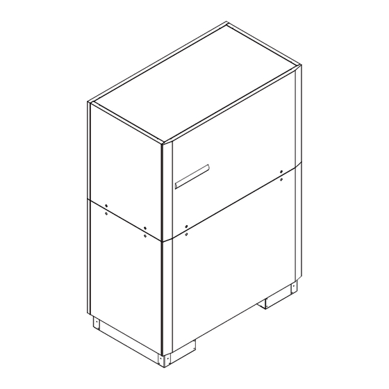
After the transport, the transport securing device is to be re- moved on either side at the bottom of the unit. ATTENTION! The transport securing device is to be removed prior to commissioning. Control Evaporator Condenser Compressor Transport securing devices Filter drier www.dimplex.de... -
Page 5: Installation
Installation Heating water minimum flow rate The heating water minimum flow rate through the heat pump must be assured in all operating states of the heating system. 6.1 General Information This can be accomplished, for example, by installing a differential pressure-free manifold or an overflow valve. -
Page 6: Commissioning
15° C 20° C 14 K 21° C 25° C 15 K Any malfunctions occurring during operation are displayed on the heat pump controller and can be corrected as described in the operating manual of the heat pump controller. www.dimplex.de... -
Page 7: Care/Cleaning
Care/Cleaning 10 Malfunctions / Troubleshooting 9.1 Care This heat pump is a quality product and designed for trouble- and The heat pump is maintenance-free. To prevent malfunctions maintenance-free operation. In the event that a malfunction oc- due to sediments in the heat exchangers, care must be taken curs nevertheless, it will be indicated on the display of the heat that no im-purities can enter the heat source system and the pump controller. -
Page 8: Equipment Data
12 Equipment Data Device information for brine-to-water heat pumps (heating only) Type and order code SI 40HS Design Degree of protection according to EN 60 529 IP 21 Installation location Indoors Performance data Operating temperature limits: Heating water flow °C... -
Page 9: Anhang / Appendix / Annexes
3.4 Legende / Legend / Légende........................A-VII Hydraulisches Prinzipschema / Hydraulic block diagrams / Schéma hydraulique .... A-VIII 4.1 Darstellung / Schematic view / Représentation schématique..............A-VIII 4.2 Legende / Legend / Légende.........................A-IX Konformitätserklärung / Declaration of Conformity / Déclaration de conformité ....A-X www.dimplex.de... -
Page 10: Maßbild / Dimensioned Drawing / Schéma Coté
1 Maßbild / Dimensioned drawing / Schéma coté A-II... -
Page 11: Diagramme / Schematics / Diagrammes
2 Diagramme / Schematics / Diagrammes www.dimplex.de A-III... -
Page 12: Stromlaufpläne / Wiring Diagrams / Schémas Électriques
3 Stromlaufpläne / Wiring diagrams / Schémas électriques 3.1 Steuerung / Control / Commande A-IV... -
Page 13: Last / Load / Charge
3.2 Last / Load / Charge www.dimplex.de... -
Page 14: Anschlussplan / Terminal Diagram / Schéma De Branchement
3.3 Anschlussplan / Terminal diagram / Schéma de branchement A-VI... -
Page 15: Legende / Legend / Légende
–––––– werksseitig verdrahtet Wired ready for use câblé départ usine - - - - - - bauseits bei Bedarf anzuschließen To be connected by the customer as required à raccorder par le client au besoin www.dimplex.de A-VII... -
Page 16: Hydraulisches Prinzipschema / Hydraulic Block Diagrams / Schéma Hydraulique
4 Hydraulisches Prinzipschema / Hydraulic block diagrams / Schéma hydraulique 4.1 Darstellung / Schematic view / Représentation schématique A-VIII... -
Page 17: Legende / Legend / Légende
Sensor for heating circuit 2 Sonde 2e circuit de chauffage Fühler 3. Heizkreis Sensor for heating circuit 3 Sonde 3e circuit de chauffage Elektroverteilung Electrical distribution system Distributeur courant électrique Kaltwasser Cold water Eau froide Warmwasser Hot water Eau chaude www.dimplex.de A-IX... -
Page 18: Konformitätserklärung / Declaration Of Conformity / Déclaration De Conformité
5 Konformitätserklärung / Declaration of Conformity / Déclaration de conformité... - Page 19 Glen Dimplex Deutschland GmbH Irrtümer und Änderungen vorbehalten. Geschäftsbereich Dimplex Subject to alterations and errors. Am Goldenen Feld 18 Sous réserve d’erreurs et modifications. D-95326 Kulmbach +49 (0) 9221 709 565 www.dimplex.de...
Need help?
Do you have a question about the SI 40HS and is the answer not in the manual?
Questions and answers