Table of Contents
Advertisement
Quick Links
Advertisement
Table of Contents

Summary of Contents for Zynex Medical M-Wave
- Page 1 M-Wave User’s Manual...
-
Page 3: Table Of Contents
M-Wave Table of Contents Contact Information / Customer Service / Supplies / Support About the M-Wave Safety Information Service and calibration Electrodes and Lead Wires Setup Programming Instructions Controls Device Operating Instructions Electrode Placement Guide Indications, Contraindications and Warnings Precautions and Adverse Reactions... -
Page 4: Contact Information / Customer Service / Supplies / Support
Questions regarding insurance benefits and covered benefits for Durable Medical Equipment (DME) or questions about an Explanation of Benefits form you received in the mail FAX NUMBER 800-495-6695 855-845-5941 MAILING ADDRESS Zynex Medical, Inc. 9655 Maroon Circle Englewood, CO 80112 EMAIL info@zynex.com WEBSITE www.zynex.com... -
Page 5: About The M-Wave
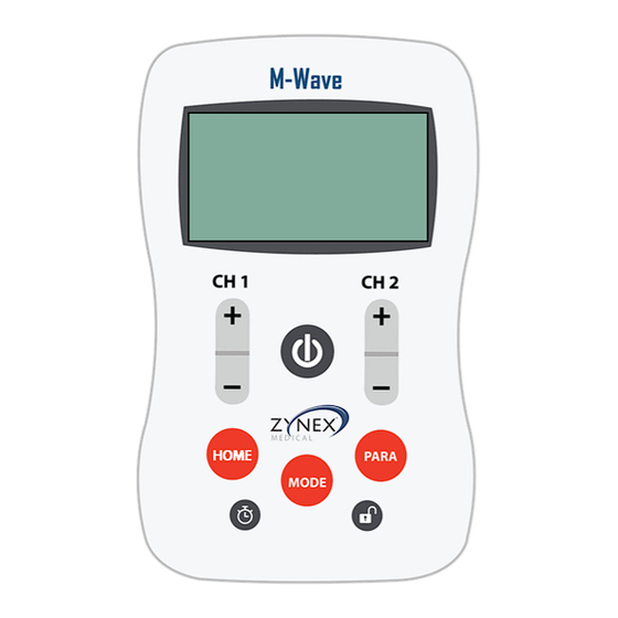
The M-Wave is an easy-to-use NeuroMuscular Electrical Stimulator (NMES) designed to accurately deliver the desired intensity and frequency of electrical current using modern state-of-the-art technology. M-Wave is one of the safest stimulators in the world with safety features such as an electrode alarm, level locking, and a guaranteed constant current. -
Page 6: Safety Information
Internally Powered Equipment When the M-Wave is powered by the internal, 9 VDC, MN1604, battery it is classified as Internally Powered Equipment. Class II Medical Equipment When powered by the external, 12 VDC, medical grade, power supply, the M-Wave is classified as Class II Medical Electrical (ME) Equipment. - Page 7 Safety Information Symbols Safety symbols shown on this device above are defined below. On/Off. This symbol indicates that the labeled switch electronically cycles the DC power on and off for part of the equipment. Note: To disconnect the external power supply, unplug the power cord of the supplied AC adapter from the AC main outlet.
-
Page 8: Service And Calibration
Service and Calibration Do not remove the cover. There are no user serviceable parts. Refer all service requests to authorized personnel. No modification of the equipment is allowed. No preventative inspections are required. Factory testing and calibration ensure equipment accuracy and response. -
Page 9: Electrodes And Lead Wires Setup
Electrode and Lead Wire Setup Step 1 Open electrode package and remove electrodes from package. Keep electrodes on plastic backing. Note: Zynex Medical electrodes are recommended for use with the M-Wave. See additional accessories on page 43. Electrode Connector Plastic Backing... - Page 10 M-Wave Electrode and Lead Wire Setup (continued) Step 3 Remove each electrode from the plastic backing and place on the treatment site according to the type of modality selected. Electrode Arrangement Using both channels is optional. NMES: NMES Example Up and Down Pattern...
- Page 11 M-Wave Electrode and Lead Wire Setup (continued) Step 4 Plug lead wires into the top of the M-Wave while carefully observing their orientation. NMES modality requires one or both lead wires (channel 1 & Step 5 Proceed to page 16 to start treatment or page 12 to program device.
-
Page 12: Programming Instructions
M-Wave Device Programming Instructions Place electrodes on the skin prior to turning on this device. Turn device on by pressing the black On/Off button Select desired settings by pressing the “HOME”, “MODE”, or “PARA” button once. Continue to press the selected settings button until desired program is displayed. -
Page 13: Controls
M-Wave Device Controls Lead Wire Connection Lead Wire Connection Channel 2 Channel 1 Display Uses electricity from wall A/C Adapter Input Turns Unit On/Off On/Off Button Channel 2 Intensity Control Channel 1 Intensity Control Up and Down Button Up and Down Button... - Page 14 Device Controls Turn Unit On and Off : Press the power button. The display will light up. Press the power button again to turn the unit off. If no controls have been touched for five minuets with a stimulation level lower than 3 mA the device will automatically turn off.
- Page 15 Device Controls Setting Waveform Mode : Press the MODE settings button until “WAVEFORM” appears. Use the up and down buttons for either channel to select either Biphasic (AC) or Monophasic (DC) waveforms. Setting Stimulation Output Mode : Press the MODE settings button until “OUTPUT”...
-
Page 16: Device Operating Instructions
Before starting treatment electrodes must be placed on the treatment site and lead wires and electrodes connected to this device. See pages 9-11 and 17-31 for examples. Turn M-Wave on by pressing On/Off button once. Up button Increase intensity by pressing Channel 1 until a strong but comfortable stimulation level is felt. -
Page 17: Electrode Placement Guide
Electrode Placement Guide IMPORTANT NOTES: Consult with a physician for treatment and electrode placement. The following M-Wave NMES general electrode placements are for reference only. Exact electrode placement may require some trial and error using low level stimulation. Shoulder Subluxation / Abduction Patient Position: Sitting or standing with the affected arm draped at the side. - Page 18 Wrist and Finger Flexion Patient Position: The patient should be seated comfortably in a chair, leaning back, with the arm placed on the legs as comfortable as possible. Electrode Placement: With palm facing up, place one electrode on the bottom of the forearm (flexor group), one inch from the elbow crease.
- Page 19 Elbow Flexion - Front Patient Position: Standing or sitting with the affected arm draped off the side of the chair. Electrode Placement: Place one electrode high on the biceps muscle (front of upper arm). Place the other electrode two (2) inches above the elbow crease. Electrode Electrode Elbow Extension - Back...
- Page 20 Ankle Dorsiflexion Patient Position: The patient should be in a seated position with the affected foot resting on the floor and the leg bent at a 90° angle. Electrode Placement: Place one electrode high on the outside of lower leg 3-4 inches below the knee and one (1) inch away from the shinbone.
- Page 21 Knee Extension - Front Patient Position: The patient should be in a seated position with the affected foot resting on the floor and the leg bent at a 90° angle. Electrode Placement: Place one electrode high on the mid-outer thigh. Place the other electrode on the inner thigh three inches above the knee.
-
Page 22: Indications, Contraindications And Warnings
Therefore its output voltage, current, and power are dependent upon the load as well as the pulse width and frequency of the output waveform. The maximum peak voltage that the M-Wave can produce is 100 V (1000 Ω load). - Page 23 Therefore, the displayed mA value on the M-wave device is in reference to expected mA assuming a 1000 Ω load. The maximum output power that the M-Wave can produce is 0.6 W per channel into a 1000 Ω load, 1.2W total.
- Page 24 M-Wave Warnings Neuromuscular Electrical Stimulation (NMES) Warnings (Continued) Stimulation should not be applied over the neck or mouth. Severe spasm of the laryngeal and pharyngeal muscles may occur and the contractions may be strong enough to close the airway or cause difficulty in breathing.
-
Page 25: Precautions And Adverse Reactions
Precautions and Adverse Reactions Safety References Zynex Medical, Inc. is only responsible for the safety, reliability, and function of this device when repairs and adjustments have been made by persons authorized by Zynex Medical, Inc., and this device is used in accordance with the user’s manual. -
Page 26: Troubleshooting
Press UNLOCK button until the “Lock” icon on the pressed, a “Lock” icon display disappears. appears on the display and the M-Wave remains unresponsive. Pressing the channel 1 discontinue use of this device and return it to the button causes channel 2 manufacturer for replacement. -
Page 27: Specifications And Accessories
M-Wave Specifications and Accessories Neuromuscular Electrical Stimulation (NMES) Amplitude: 0-100 mA Frequency: 4-100 Hz, Pulse Width: 50-300 μs On-Time: 0.5 to 30 sec., Off-Time: 0.1 to 60 sec., Ramp Up: 0.1 to 6 sec., Ramp Down: 0.1 to 6 sec.,... -
Page 28: Electrodes, Batteries, Cleaning
Please dispose of used batteries properly. AC Adapter The M-Wave is supplied with an AC adapter that is plugged into the left side of this device and then into a 120 or 230 VAC electrical outlet. Note: The supplied AC adapter, Zynex P/N 200109, mains power requirement is 100-240 VAC, 50-60 Hz, 0.3A... -
Page 29: Warranty
During that time, Zynex Medical, Inc. will replace, at its sole discretion, the M-Wave device that has been used in a standard manner. This warranty does not cover misuse or use contrary to the operating instructions supplied. -
Page 30: Emissions And Immunity Test Specifications
M-Wave Emissions and Immunity Test Specifications Phenomenon Basic EMC standard or test Method Professional healthcare Home healthcare facility environment environment Emissions Radiated RF Emissions CISPR 11 CISPR 11 Conducted RF Emissions CISPR11 CISPR11 Harmonic Distortion IEC 61000-3-2 IEC 61000-3-2 Voltage fluctuations and flicker... - Page 31 M-Wave Emissions and Immunity Test Specifications Phenomenon Basic EMC standard Immunity test levels or test Method Professional healthcare Home healthcare facility environment environment Patient coupling port Electrostatic discharge IEC 61000-4-2 ± 8kV contact ± 2kV, ± 4kV, ± 8kV, ± 15kV air...
- Page 32 Zynex Medical, Inc. 9655 Maroon Circle Englewood, CO 80112 Phone: 1-800-495-6670 Fax: 1-800-495-6695 Internet: www.zynex.com Email: info@zynex.com P/N 301200 Rev.9.5...
Need help?
Do you have a question about the M-Wave and is the answer not in the manual?
Questions and answers