
Subscribe to Our Youtube Channel
Related Manuals for Federal Signal Corporation Pathfinder PF400


Summary of Contents for Federal Signal Corporation Pathfinder PF400
- Page 1 Pathfinder PF400 and PF400Q ® Installation and Maintenance Instructions 25500840 Rev A1 0124 Printed in U.S.A. © Copyright 2023-2024 Federal Signal Corporation...
- Page 2 A copy of this limited warranty can also be obtained by written request to Federal Signal Corporation, 2645 Federal Signal Drive, University Park, IL 60484, email to info@fedsig.com or call +1 708-534-3400.
-
Page 3: Table Of Contents
Contents Safety Messages for Installers and Operators ......................5 Safety Messages to Installers of Sound/Light Systems ......................5 Safety Messages to Operators of Sound/Light Systems ....................8 An Overview of the Pathfinder PF400 and PF400Q ....................10 ® Siren, PA, and Speakers ................................10 Light Bars and SignalMaster Control ............................ - Page 4 Tables Table 1 System Specifications ..............................12 Table 2 Siren Specifications ................................. 12 Table 3 Relay Specifications ................................ 12 Table 4 PF400Q, PF400QS17B, PF400R, and PF400S17B Kit Contents ................13 Table 5 PF400QAMP Kit Contents ..............................14 Table 6 PF400QH and PF400H Kit Contents...........................14 Table 7 Channels and Output ..............................
-
Page 5: Safety Messages For Installers And Operators
Safety Messages for Installers and Operators Safety Messages for Installers and Operators For your safety, read and understand this manual thoroughly before installing, operating, and servicing the PF400 siren amplifier/relay module. The safety messages presented in this chapter and throughout the manual are reminders to exercise extreme care at all times. - Page 6 Safety Messages for Installers and Operators During Installation • Do NOT get metal shavings inside the product. Metal shavings in the product can cause the system to fail. If drilling must be done near the unit, place an ESD-approved cover over the unit to prevent metal shavings from entering the unit.
- Page 7 Safety Messages for Installers and Operators • Locate the control head so the vehicle, controls, and microphone can be operated safely. • When drilling into a vehicle structure, ensure that both sides of the surface are clear of anything that could be damaged. All drilled holes should be deburred and all sharp edges should be smoothed.
-
Page 8: Safety Messages To Operators Of Sound/Light Systems
Safety Messages for Installers and Operators Safety Messages to Operators of Sound/Light Systems People’s lives depend on your safe operation of Federal Signal products. It is important to read and follow all instructions shipped with the products. Listed below are some other important safety instructions and precautions you should follow: •... - Page 9 Safety Messages for Installers and Operators mounting surface. An improperly secured light could fall off of the vehicle, causing injury and damage. • The holding power of magnetic mounting systems is dependent upon surface finish, surface flatness, and thickness of the steel mounting surface. Therefore, to promote proper magnetic mounting: •...
-
Page 10: An Overview Of The Pathfinder Pf400 And Pf400Q
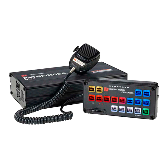
Siren, PA, and Speakers The Pathfinder PF400/PF400Q produces wail, yelp, priority, and an air horn sound by default. The horn-ring transfer feature enables the driver to control siren tones by pressing the horn button. Public address is available with the Federal Signal microphone, which is included with the system. -
Page 11: Light Bars And Signalmaster ® Control
An Overview of the Pathfinder® PF400 and PF400Q Light Bars and SignalMaster Control ® Compatible light bars include full featured, serially-controlled Federal Signal Legend ® , Valor ® , Allegiant ® , Navigator ® , Vision ® SLR and Integrity ® , as well as the CN SignalMaster ™... -
Page 12: System Specifications
An Overview of the Pathfinder® PF400 and PF400Q System Specifications Table 1 System Specifications Input Voltage 11 Vdc to 28 Vdc Polarity Negative ground only Operating Temperature Range -40°C to +80°C (-40°F to +176°F) (all relays at 50% power) Standby Current Less than 0.1 A Max Input Current 90 A (siren and relays) -
Page 13: Kit Contents
An Overview of the Pathfinder® PF400 and PF400Q Kit Contents The Kit Contents tables list the parts included with each kit. Note that each kit contains only one kind of controller. After unpacking the kit, examine it for damage that may have occurred in transit. If the product has been damaged, file a claim immediately with the carrier stating the extent of damage. -
Page 14: Table 5 Pf400Qamp Kit Contents
An Overview of the Pathfinder® PF400 and PF400Q Table 5 PF400QAMP Kit Contents Qty Description Part Number 400-Watt Siren Amplifier* 862303915-Q PF400 Mounting Bracket 862304026 RS485 25 ft (7.62 m) Cable Assembly 1751357-02 Pathfinder Relay Wire Assembly 17501359 Pathfinder I/O Wire Assembly 17501360 PF400 Audio Out Wire Assembly 17502532... -
Page 15: Wiring The Siren
Wiring the Siren Wiring the Siren General Guidelines for Wiring the PF400/PF400Q on a Vehicle HIGH CURRENT ARCING: Do not connect this system to the vehicle battery until ALL other electrical connections are made and you have verified that no shorts exist. High current conductors can cause hazardous sparks or burning wire, resulting in electrical fires. - Page 16 Wiring the Siren Twelve-Conductor Wire Assembly for the Relay Outputs The cable is FS# 17501359. Each conductor is 16 AWG; its construction is described below. NOTE: Cable tie the wires 6 inches from the connector. Component Qty Vendor Vendor Part # Description Position Color...
- Page 17 Wiring the Siren Eight-Conductor Wire Assembly for the Speaker Outputs The cable is FS# 17502532. Each conductor is 18 AWG; its construction is described below. Component Qty Vendor Vendor Part # Description Position Color Function Connector Molex 1722583108 Conn Rcpt Hsg 8 POS 3.50 mm Brown Speaker 1- Terminal...
-
Page 18: Figure 1 Siren Connections
Wiring the Siren Figure 1 Siren Connections BAT (-) SIREN (+) LIGHTING (+) Pathfinder PF400 and PF400Q ® Federal Signal www.fedsig.com... -
Page 19: Overview Of The Pf400 Connections
Wiring the Siren Overview of the PF400 Connections To prepare the vehicle for connecting the Convergence Network system: 1. After planning where to route the wires and cables for the system components — such as Federal Signal warning lights, directional lights, and speakers — drill the holes for the wiring. -
Page 20: Horn Ring Transfer
Wiring the Siren (as well as the input polarity) can be configured with the Convergence Network Configuration Software. If using FS Vehicle Integration to detect the park event, this wire is not used. Fold and seal. Horn Ring Transfer DETERMINE CURRENT FOR HORN: The horn ring transfer circuit of the siren can switch a maximum of 5 A. -
Page 21: Speaker Connections
Wiring the Siren Speaker Connections The Pathfinder ® PF400/PF400Q is designed to operate with different speaker configurations. It can operate one to four 11-ohm impedance, 100 W speakers. If using more than one 11-ohm impedance, 100 W speakers, each must be wired on a separate channel of the amplifier and in phase for proper operation. -
Page 22: Radio Re-Broadcast
Wiring the Siren The Pathfinder PF400 siren is designed to detect speaker faults. Diagnostic LEDs available on the front of the keypad can provide the operating status of channels 1 and 2. The LEDs are fully programmable and can be set to steady burn or flash when the siren detects a fault or normal operation for each individual speaker. -
Page 23: Mounting The Pf400
Mounting the PF400 Mounting the PF400 The next step in the installation after wiring and connecting the system is to permanently mount the siren in the vehicle. Verify that the mounting locations you selected earlier are safe for installing these components. Review the following precautions before mounting the equipment. -
Page 24: Figure 2 Pf400 Dimensions
Mounting the PF400 Figure 2 PF400 Dimensions 11.09in 28.17cm 4.00in 10.16cm 2.00in 5.08cm 6.00in 15.24cm 7.20in 18.29cm 8.00in 20.32cm 2.50in 6.35cm Pathfinder PF400 and PF400Q ® Federal Signal www.fedsig.com... -
Page 25: Mounting The Siren
Mounting the PF400 Mounting the Siren To mount the siren: 1. Use the bracket as a template to mark the centers of the two mounting holes. DRILLING PRECAUTIONS: Before drilling holes, check the area into which you plan to drill to ensure that you do not damage vehicle components. All drilled holes should be deburred and all sharp edges should be smoothed. -
Page 26: Figure 3 Bracket Attached To Back Of Pf400 Control Head
Mounting the PF400 5. Secure the mounting bracket to the mounting surface with user-supplied #10 thread-forming screws. Figure 3 Bracket Attached to Back of PF400 Control Head Figure 4 Bracket Attached to Back of PF400Q Control Head 6. To adjust the angle of the control head, loosen the hinge screws, tilt the control head forward or backward, and then securely tighten the screws Pathfinder PF400 and PF400Q... -
Page 27: Testing The Pf400 Installation
Testing the PF400 Installation Testing the PF400 Installation The PF400 is programmed with a default configuration that you can use to quickly check your initial installation system before you configure the system. Test all vehicle functions, including horn operation, vehicle safety functions, and vehicle lighting systems for proper operation. -
Page 28: Table 11 Pf400Q Input Default Programming
Testing the PF400 Installation Table 11 PF400Q Input Default Programming Button Default Function Polarity Ignition System Enable, Immediate system shutdown (no delay) ignition Park Siren Mute Input 1 Air Horn Input 2 Q Siren Momentary Cycle Input 3 Q Siren Momentary Brake Input 4 No Function Horn Ring When MANUAL is Active, Air Horn... -
Page 29: Table 12 Pf400Qr Remote Default Programming
Testing the PF400 Installation Figure 6 PF400R/PF400QR Controller BTN 1 BTN 2 BTN 3 BTN 4 BTN 5 BTN 6 BTN 7 BTN 8 BTN 9 Table 12 PF400QR Remote Default Programming Button Default Function Light Bar — Pattern 10, Front Cutoff Slide Switch 1 ILS —... -
Page 30: Table 13 Pf400Qr Remote Input Default Programming
Testing the PF400 Installation Table 13 PF400QR Remote Input Default Programming Button Default Function Polarity Ignition System Enable, Immediate system shutdown (no delay) ignition Park Siren Mute Relay 14 OFF Flashing Takedown Cutoff (LB/ILS/CNSM) Input 1 Remote SS1 Activation Input 2 Remote SS2 Activation Input 3 Remote SS3 Activation... -
Page 31: Table 14 Pf400R Remote Default Programming
Testing the PF400 Installation Table 14 PF400R Remote Default Programming Button Default Function Light Bar — Pattern 10, Front Cutoff Slide Switch 1 ILS — Rear Pattern 10 CNSM- Rear Pattern 10 Relays 1 and 13 ON Slide Switch 2 Light Bar —... -
Page 32: Table 15 Pf400R Remote Input Default Programming
Testing the PF400 Installation Table 15 PF400R Remote Input Default Programming Button Default Function Polarity Ignition System Enable, Immediate system shutdown (no delay) ignition Park Siren Mute Relay 14 OFF Flashing Takedown Cutoff (LB/ILS/CNSM) Input 1 Remote SS1 Activation Input 2 Remote SS2 Activation Input 3 Remote SS3 Activation... -
Page 33: Table 16 Pf400Qs17B Switch Default Programming
Testing the PF400 Installation Figure 7 PF400/PF400Q 17-Button Controller Table 16 PF400QS17B Switch Default Programming Switch Default Function Light Bar — Pattern 10, Front Cutoff Slide Switch 1 ILS — Rear Pattern 10 CNSM- Rear Pattern 10 Relays 1 and 13 ON Slide Switch 2 Light Bar —... -
Page 34: Table 17 Pf400Qs17B Input Switch Default Programming
Testing the PF400 Installation Table 17 PF400QS17B Input Switch Default Programming Button Default Function Polarity Ignition System Enable, Immediate system shutdown (no delay) ignition OFF Park Siren Mute Relay 14 OFF Button 17 OFF Flashing Takedown Cutoff (LB/ILS/CNSM) Input 1 Remote SS1 Activation Input 2 Remote SS2 Activation... -
Page 35: Table 18 Pf400S17B Switch Default Programming
Testing the PF400 Installation Table 18 PF400S17B Switch Default Programming Switch Default Function Light Bar — Pattern 10, Front Cutoff Slide Switch ILS — Rear Pattern 10 CNSM- Rear Pattern 10 Relays 1 and 13 ON Slide Switch Light Bar — Pattern 17 ILS —... -
Page 36: Table 19 Pf400S17B Input Switch Default Programming
Testing the PF400 Installation Table 19 PF400S17B Input Switch Default Programming Button Default Function Polarity Ignition System Enable, Immediate system shutdown (no delay) ignition OFF Park Siren Mute Relay 14 OFF Flashing Takedown Cutoff (LB/ILS/CNSM) Input 1 Remote SS1 Activation Input 2 Remote SS2 Activation Input 3... -
Page 37: Table 20 Pf400Qh Hand-Held Default Programming
Testing the PF400 Installation Figure 8 PF400H/PF400QH Handheld Controller Table 20 PF400QH Hand-Held Default Programming Button Default Function Light Bar — Pattern 10, Front Cutoff Button 1 ILS — Rear Pattern 10 CNSM — Rear Pattern 10 Relays 1 and 13 ON Button 2 Light Bar —... -
Page 38: Table 21 Pf400Qh Hand-Held Input Default Programming
Testing the PF400 Installation Table 21 PF400QH Hand-Held Input Default Programming Button Default Function Polarity Ignition System Enable, Immediate system shutdown (no delay) ignition OFF Park Siren Mute Relay 14 OFF Flashing Takedown Cutoff (LB/ILS/CNSM) Input 1 Remote Button1 Activation Input 2 Remote Button 2 Activation Input 3... -
Page 39: Table 22 Pf400H Hand-Held Default Programming
Testing the PF400 Installation Table 22 PF400H Hand-Held Default Programming Button Default Function Light Bar — Pattern 10, Front Cutoff Button 1 ILS — Rear Pattern 10 CNSM — Rear Pattern 10 Relays 1 and 13 ON Button 2 Light Bar — Pattern 17 ILS —... -
Page 40: Table 23 Pf400H Hand-Held Input Default Programming
Testing the PF400 Installation Table 23 PF400H Hand-Held Input Default Programming Button Default Function Polarity Ignition System Enable, Immediate system shutdown (no delay) ignition OFF Park Siren Mute Relay 14 OFF Flashing Takedown Cutoff (LB/ILS/CNSM) Input 1 Remote Button 1 Activation Input 2 Remote Button 2 Activation Input 3... -
Page 41: Control Head Legends And Safety Messages
Control Head Legends and Safety Messages Control Head Legends and Safety Messages To complete the installation, the kit includes: • A scored sheet of replaceable keypad legends that identify the functions of the control head buttons. Before installing the legends, configure the operation of the control head with the Convergence Configuration Software. -
Page 42: Applying The Siren Safety Labels In The Vehicle
Control Head Legends and Safety Messages Applying the Siren Safety Labels in the Vehicle The kit includes a sheet of two labels with siren safety messages (part no. 1612339). See Figure 7. These labels must be installed in the vehicle in which the system is installed. -
Page 43: Safety Messages
Safety Messages Safety Messages Safety Messages to Personnel Servicing Federal Electronic Sirens People’s lives depend on your proper servicing of Federal Signal products. It is important to read and follow all instructions shipped with the products. Listed below are some other safety instructions and precautions you should follow: •... -
Page 44: Servicing The Pf400
Servicing the PF400 Servicing the PF400 Federal Signal recommends that the siren be returned to your local distributor or Federal Signal for service. External components, such as cabling, are available as replacement parts. See Table 23 on page 45. Other than the slide switch in the siren, there are no other user-serviceable parts within the unit. -
Page 45: Table 24 Service Parts
Servicing the PF400 Table 24 Service Parts Description Part Number - Part Number - PF400Q PF400 PF400Q with e-Q2B Controller PF400Q PF400 or PF400Q with 17-Button Controller PF400QS17B PF400S17B PF400 and PF400Q with Handheld Controller PF400QH PF400H Amplifier (amplifier only) PF400QAMP Remote Controller PF400R... -
Page 46: Getting Technical Support And Service
Getting Technical Support and Service Getting Technical Support and Service For technical support and service, please contact: Service Department Federal Signal Corporation Phone: 1-800-433-9132 Email: empserviceinfo@fedsig.com www.fedsig.com Pathfinder PF400 and PF400Q ® Federal Signal www.fedsig.com... -
Page 47: Getting Repair Service
Distributor or Manufacturer’s Representative. Provide a brief explanation of the service requested or the nature of the malfunction. Address all communications and shipments to the following: Federal Signal Corporation Service Department 2645 Federal Signal Drive University Park, IL 60484-3167 Installation and Maintenance Instructions... - Page 48 2645 Federal Signal Drive University Park, Illinois 60484 www.fedsig.com Customer Support Police/Fire-EMS: 800-264-3578 • +1 708 534-3400 Work Truck: 800-824-0254 • +1 708 534-3400 Technical Support 800-433-9132 • +1 708 534-3400...
Need help?
Do you have a question about the Pathfinder PF400 and is the answer not in the manual?
Questions and answers