Table of Contents
Advertisement
Quick Links
Advertisement
Table of Contents

Related Manuals for MiniMax UniVario FMX5000 IR Ex

Summary of Contents for MiniMax UniVario FMX5000 IR Ex
- Page 1 Instructions for use Flame detector ® UniVario FMX5000 IR Ex...
- Page 2 IMPORTANT! Read this document before starting any work! This document is a mandatory part of the product and should therefore always be stored freely accessible and for further usage. Original document Minimax GmbH Industriestr. 10/12 23840 Bad Oldesloe Germany Phone: +49 4531 803-0 Fax: +49 4531 803-248 www.minimax.com...
-
Page 3: Table Of Contents
Table of contents Table of contents General........................... About this document..................Validity......................Copyright....................... Intended use....................Safety..........................Safety and warning notices................Intended use....................Safe operation....................Qualification of personnel................Responsibility of the operator..............Fields of use....................Design and function....................General description of the function............. Detector types..................... - Page 4 Table of contents ® 3.13 UniVario KMX5000 AP Ex communication module (option)...... 3.14 Self-monitoring.................... Project planning information..................Maximum number of detectors on a detector line........Classification....................Room monitoring as per VdS 2095: 2010-05 (07)........Sources of interference................Impairment of fire sensitivity............... Configuration.......................
- Page 5 Table of contents ® UniVario KMX5000 AP Ex communication module........6.9.1 Installation of communication module............6.9.2 Example addressing................... 6.9.3 Address communication module..............Commissioning......................Preparation for start-up................Carrying out start-up................... Maintenance......................... Test intervals....................Inspection....................Test triggering..................... 8.3.1 Execution....................Function check.................... 8.4.1 Prerequisites....................
- Page 6 Table of contents 12.2 Mechanical data..................12.3 Electrical data..................... 12.4 Climatic data....................12.5 Approvals / conformity................Packaging, Storage and Transport................13.1 Transport and Packaging................13.2 Storage....................... Appendix........................® Instructions for use / UniVario FMX5000 IR Ex / 912311 / 07-2023 / en_US...
-
Page 7: General
General General About this document This document enables the intended use of the product described. Observing all specified instructions and safety instructions is the prerequisite for safe work. Fur- thermore, the local accident prevention regulations and general safety conditions for the use of the product are also applicable. -
Page 8: Safety
Safety Safety Safety and warning notices Safety and warning notices are marked with symbols in this document. The introduc- tory signal words express the respective extent of the danger. DANGER The signal word describes a danger with a high risk level. If the danger is not avoided, it will result in death or serious injury. -
Page 9: Safe Operation
Safety Safe operation The products described here exhibit a high degree of operational safety. However, the products can pose hazards or impair the system or other property if used improperly or for other than their intended purpose. The products must only be used in an undamaged and fully functional condition. -
Page 10: Responsibility Of The Operator
Safety ● They have read and understood this document including the safety instructions and warning notices. ● They are familiar with basic regulations on occupational safety and accident prevention. ● They have been given instruction on handling the product and the entire system. The various tasks described in this document require that the persons responsible for them have different qualifications. -
Page 11: Fields Of Use
Safety The operator commits to allow only specialist personnel to work at or with the detector. Such personnel shall - be familiar with basic regulations on occupational safety and accident prevention, - have been given instruction on handling the detector and the entire system - and have read and understood the operating manual, including the safety and warning notices. - Page 12 Safety Field of application - FMX5000 IR SF All detectors are available in silicone-free versions and thus free of substances which inhibit paint adhesion. For example, these detectors can be used in paint finishing plants. INFORMATION Ensure that the assembly and installation accessories as well as the detector base are also silicone-free during assembly and installation.
-
Page 13: Design And Function
Design and function Design and function General description of the function FMX5000 IR Ex flame detectors have three optical input channels and react to flames from fuels containing carbon. Depending on the respective version, the detectors are suitable for indoor and outdoor use and approved for use in the following explosion hazard areas: Zone 0, 1, 2, 20, 21 and 22. -
Page 14: Detector Types
Design and function Front and rear view 1 Terminal strip 2 Socket strip Ä Chapter 5 “Configuration” 3 DIP switch on page 31 Ä Chapter 4 Temperature measuring pad 3.10 “Temperature measuring pad” on page 20 Ä Chapter 3.11 “Device 5 Nameplate markings”... -
Page 15: Detector Type Fmx5000 Ir Ex
Design and function 3.2.1 Detector type FMX5000 IR Ex Intrinsically safe flame detector with integrated function test of the optical channels via IR emitter. Aluminum housing. This detector is also available as a silicone-free version. 3.2.2 Detector type FMX5000 IR Ex ST Intrinsically safe flame detector with integrated function test of the optical channels via IR emitter. - Page 16 Design and function Detection distance solid-material fires Fuel FMX5000 IR FMX5000 IR FMX5000 IR FMX5000 IR FMX5000 UV Class X Class 1 Class 2 Class 3 Class 1 (50 m) Cotton 100 g, 10 m 7.5 m 10 m fluffed up* Cotton 500 g, 15 m 10 m...
-
Page 17: Viewing Range
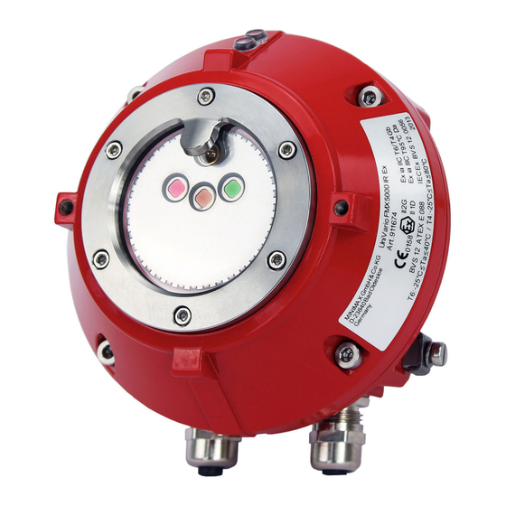
Design and function Viewing range The viewing range of the detector is shown in the following figure. The relative sensitivity is given (in percent). FMX5000 IR Ex viewing range Status indicators 1 Alarm indicator (red) 2 Operation indicator (green) or fault indi- cator (yellow) Fig. -
Page 18: Alarm Signaling
Design and function The status indicators show that operation is normal or if an alarm or fault exists. The detector has a red status indicator as well as a two-color green/yellow status indicator. Status Indicator Description Miscellaneous indicator behavior green flashes every Correct operation. -
Page 19: Fault Signaling
Design and function Fault signaling If a fault condition is met, the internal fault circuit is activated and an additional fault current flows . This increase in current allows a connected evaluation unit to recognize that a detector is in a fault state. The fault indicator of the detector lights up. -
Page 20: Temperature Measuring Pad
The nameplate (on the rear of the detector) contains at least the following informa- tion: Manufacturer and address Minimax GmbH D-23840 Bad Oldesloe Detector type UniVario FMX5000 IR Ex CE marking ® Instructions for use / UniVario FMX5000 IR Ex / 912311 / 07-2023 / en_US... -
Page 21: Nameplate On Fmx5000 Ir Ex
The nameplate of the FMX5000 IR Ex ST (on the outside of the detector) contains at least the following information: Manufacturer and address Minimax GmbH D-23840 Bad Oldesloe Detector type UniVario FMX5000 IR Ex ST CE marking e 0158 ® Instructions for use / UniVario FMX5000 IR Ex / 912311 / 07-2023 / en_US... -
Page 22: Detector Base
Design and function Explosion protection marking, category x II 1G Ex ia IIC T4 Ga 1G (gas) x II 1G Ex ia IIC T6 Ga 95 °C Da Explosion protection marking, category x II 1D Ex ia IIIC T 1D (dust) x II 1D Ex ia IIIC T 105 °C Da Number of type examination certificate... -
Page 23: Univario ® Mx5000 Detector Base
Design and function ® 3.12.1 UniVario MX5000 detector base Fig. 8: MX5000 M20 Ex detector base 1 Terminal block (8-pole) 2 Cable entry with cable gland 3 Potential equalization terminal (Ex variants only) Detector Cable gland Cable diameter Equipotential base bonding terminal MX5000 Ex... -
Page 24: Univario ® Mx5000 Ex St Detector Base
Design and function The MX5000 Ex detector base has a terminal block (Fig. 8/1) and (Fig. 23) and two certified cable entries (Fig. 8/2) with M16 cable glands as well as an external equipotential bonding terminal. INFORMATION These detector bases are made of aluminum and may NOT be used for the UniVario®... -
Page 25: Univario ® Kmx5000 Ap Ex Communication Module (Option)
Design and function ® 3.13 UniVario KMX5000 AP Ex communication module (option) Individually addressable detector loop operation with an Apollo XP95-compatible protocol is possible with the communication module Ä Chapter 10.3 “Communica- tion interfaces” on page 70. The KMX5000 AP Ex has no isolator. INFORMATION With the communication module installed, conventional transmission of state condi- tions by the detector's current rise technology is deactivated! In this case, the states... -
Page 26: Project Planning Information
Project planning information Project planning information ● Coordinate the number of detectors with the area to be monitored and the kind of event to be detected. Where appropriate, observe any applicable national regulations and laws. ● KMX5000 AP Ex communication module (option): Give consideration to detector-type restrictions of the loop used during the system configuration. - Page 27 Project planning information Fig. 10: Classification NOTICE False alarm due to too high fire sensitivity The detector class should only be set as sensitive as is necessary in order to avoid false alarms. ® Instructions for use / UniVario FMX5000 IR Ex / 912311 / 07-2023 / en_US...
-
Page 28: Room Monitoring As Per Vds 2095: 2010-05 (07)
Project planning information Room monitoring as per VdS 2095: 2010-05 (07) In a rectangular room the detector must be aligned at an angle of 45° between the optical axis and wall. Fig. 11: Room monitoring as per VdS 2095: 2010-05 (07) Flame detector Maximum edge Longest path to... -
Page 29: Impairment Of Fire Sensitivity
Project planning information The inverse-square law also applies to sources of disturbance! If the radiative heat transfer of a modulated source of interference is considerably larger than the radiative heat transfer of a fire to be detected, then detection is delayed considerably or does not take place at all. - Page 30 Project planning information ° Fig. 12: Sensitivity is reduced by half at an angle of 45 NOTICE Hot surfaces in the detector viewing range can prevent fire detection. At minimum, maintain a distance of 5 m (16 ft) between hot surfaces (e.g. electrical resistance heaters, fan heaters, radiators) and the detector.
-
Page 31: Configuration
Configuration Configuration Have the work described in this section carried out only by the following persons: Personnel: Qualified specialist personnel DIP switch DIP switch settings on the detector: ● Setting the configuration DIP switch settings on the KMX5000 AP communication module: Ä... -
Page 32: Carry Out Configuration
Configuration Carry out configuration DIP switches 1 to 4: Configuration setup DIP switch 12345678 Meaning -XXXXXXX Reed switch active 1XXXXXXX Reed switch inactive X-XXXXXX Alarm latching during limit value operation / Discovery during loop operation X2XXXXXX Alarm non-latching during limit value operation / XP95 during loop operation XX-XXXXX Not currently used... -
Page 33: Installation
Installation Installation Have the work described in this section carried out only by the following persons: Personnel: Qualified specialist personnel Safety The assembly and installation work described below requires that all project plan- ning documents for the complete system as well as for the respectively valid national regulations and laws be observier, for installations in explosion hazard area e.g. -
Page 34: Preparation For Assembly
Installation INFORMATION The FMX5000 IR Ex ST is only suitable for assembly with the MX5000 mounting bracket. Preparation for assembly The assembly location has been specified based on the configuration documents. The detector has been configured in accordance with the configuration requirements Ä... -
Page 35: Bracket Mounting
Installation 6.5.1 Bracket mounting Fig. 14: FMX5000 IR Ex – Device and assembly dimensions and bracket mounting inclination angle 1 Detector is adjustable in 15° increments ® Instructions for use / UniVario FMX5000 IR Ex / 912311 / 07-2023 / en_US... - Page 36 Installation 1 Bracket screws Fig. 15: MX5000 Ex detector base for bracket mounting Drill the holes required for the mounting of the bracket. Be sure to observe the dimensions and pivot area of the detector. Mount the bracket with the suitable fastening materials. Screw the bracket to the detector base using the bracket screws (Fig.
- Page 37 Installation 1 Terminal block 2 Cable entry 3 Equipotential bonding terminal Fig. 16: MX5000 Ex detector base ® Instructions for use / UniVario FMX5000 IR Ex / 912311 / 07-2023 / en_US...
- Page 38 Installation Fig. 17: Screw the FMX5000 IR Ex to the detector base 1 Terminal block 2 Detector base 3 Detector 4 Screws ® Instructions for use / UniVario FMX5000 IR Ex / 912311 / 07-2023 / en_US...
-
Page 39: Assembly With Mounting Bracket
Installation 6.5.2 Assembly with mounting bracket Fig. 18: Assembly dimensions of MX5000 ST mounting bracket ® Instructions for use / UniVario FMX5000 IR Ex / 912311 / 07-2023 / en_US... - Page 40 Installation Fig. 19: Assembly of MX5000 ST wall mounting bracket MX5000 ST wall mounting bracket Pivot arm of MX5000 ST mounting bracket Mounting for MX5000 ST mounting bracket Socket head screw ISO 4762-M10x55-A4 Bushing for MX5000 wall bracket Washer ISO 7092-8 4-A4 Screw M8x12 for MX5000 ST bracket Screw DIN 6912-M12x30-A4 Loctite 243...
- Page 41 Installation Install wall mounting bracket (1) according to the situation at the installation location. For insulated installation, use bushings MX5000 (5). Install the wall mounting bracket vertically so that the recess for the pivot arm (10) is on the left. The four bores are designed for M8 screws stainless steel A4 ISO 4762 (11) with washers ISO 7092-8,4-A4 (6) and nuts M8-A4 (12) .
-
Page 42: Bracket Mount Installation
Installation 6.5.3 Bracket mount installation Fig. 20: FMX5000 IR Ex bracket mount installation 1 Detector 2 M5 screws 3 O-ring 4 MX5000 console Drill the holes required for installing the console. Use the console as a drilling template. Observe the dimensions of the console (Fig. 20/4) and the detector. Install the console onto the object to be monitored using the supplied tapping screws, supplied blind rivets or other suitable fastening materials. -
Page 43: Electrical Connection
Installation Place the detector (Fig. 17/3) onto the detector base (Fig. 17/2). The terminal strip of the detector must be inserted into the terminal block (Fig. 17/1). The cable entries on the detector base should face down. Screw the detector and detector base together with the screws (Fig. 17/4) supplied. -
Page 44: Maximum Terminal Resistance
Installation ● Intrinsically safe fire detectors must be connected to safety barriers that are located outside the explosion hazard area. ● If a fault line is used, an additional safety barrier must be used. ● Only use certified safety barriers with U ≤... - Page 45 Installation ● The maximum line resistance can be limited by the evaluation unit used and must never be exceeded. Information on the maximum line resistance can be found in the operating manual of the evaluation unit. ● For alarm currents which are switched on: The additional voltage drop on the line impedance must not cause the voltage on the detector terminals to fall below the permitted level.
-
Page 46: Preparation Of Cable Connection
Installation Preparation of cable connection INFORMATION Shielded cabling for the detector is not mandatory. However, the connection condi- tions of the evaluation unit used might require this. Check the operating manual of the evaluation unit. Fig. 21: Cable gland unshielded, example M16x1,5 1 Intermediate fitting 2 Cable sheath 3 Plastic insert... -
Page 47: Fasten The Cable Gland And Cable Shield
Installation 6.7.1 Fasten the cable gland and cable shield For the procedure described below, see Fig. 21 and Fig. 22. INFORMATION In the following description and in the Fig. 21 and Fig. 22, the M16 x 1.5 cable gland is described as an example. Other cable glands can deviate from this. Remove the cable gland union nut and plastic insert with seal from the detector base. -
Page 48: Connect The Complete System (Control Drawings)
Installation Connect the complete system (control drawings) Electrical connection of the detectors to associated apparatus (safety barriers) is shown as an intrinsically safe system in the drawings below (control drawings). An intrinsically safe system can consist of the interconnection of intrinsically safe devices and associated apparatus (safety barriers) investigated under the entity evaluation concept. -
Page 49: Alarm Line Wiring Diagram
Installation Installation must take place in accordance with ANSI/ISA RP12.06.01 “Installa- tion of Intrinsically Safe Systems for hazardous (classified) locations” and the ® National Electrical Code (ANSI/NFPA 70). The correct cable glands with an M16x1.5 thread must be used. Revisions of this chapter require FM approval. AEx ‘[ib]’... - Page 50 Installation Fig. 25: Alarm line wiring without a fault line with a galvanically isolated barrier 1 Fire alarm control panel 2 Alarm line 3 Safety barrier 4 Detector 1 5 Detector n 6 End-of-line resistor (EOL) ® Instructions for use / UniVario FMX5000 IR Ex / 912311 / 07-2023 / en_US...
-
Page 51: Alarm And Fault Line Wiring Diagram
Installation 6.8.2 Alarm and fault line wiring diagram Fig. 26: Alarm line wiring with a fault line and a zener barrier 1 Fire alarm control panel 2 Alarm line 3 Fault line 4 Safety barrier 5 Equipotential bonding explosion hazard area 6 Detector 1 7 Detector n 8 End-of-line resistor (EOL) - Page 52 Installation Fig. 27: Alarm line wiring with a fault line and a galvanically isolated barrier 1 Fire alarm control panel 2 Alarm line 3 Fault line 4 Safety barrier 5 Detector 1 6 Detector n 7 End-of-line resistor (EOL) INFORMATION If a fault line is used, the complete cabling must have a separately laid "-UL"...
-
Page 53: Alarm Line Wiring Diagram, External Indicator And Test/Reset Button
Installation 6.8.3 Alarm line wiring diagram, external indicator and test/reset button Fig. 28: Alarm line wiring, external indicator and test/reset button with a zener barrier 1 Fire alarm control panel 2 Alarm line 3 Safety barrier 4 External indicator 5 Equipotential bonding explosion hazard area 6 Detector 1 7 Detector n 8 End-of-line resistor... - Page 54 Installation Fig. 29: Alarm line wiring, external indicator and test/reset button with a galvanically isolated barrier 1 Fire alarm control panel 2 Alarm line 3 Fault line 4 External indicator 5 Detector 1 6 Detector n 7 End-of-line resistor 8 Test/reset button for test triggering Connection instructions The line connected to the "T/R"...
-
Page 55: Wiring Diagram Of Individually Addressable Detectors With Kmx5000 Ap Ex
Installation 6.8.4 Wiring diagram of individually addressable detectors with KMX5000 AP Ex Fig. 30: Wiring diagram – individually addressable operation in the spur at the loop 1 Loop end 2 Loop start 3 Protocol translator 4 Safety barrier 5 Detector 1 6 Detector n INFORMATION Ä... -
Page 56: Example Addressing
Installation Fig. 31: Mount the KMX5000 AP Ex communication module on the detector 1 KMX5000 AP Ex communication module 2 DIP switch on the KMX5000 AP Ex communication module 3 DIP switch on the detector 6.9.2 Example addressing Address 42 Switches 1-3-5-7 Fig. - Page 57 Installation Address DIP switch Address DIP switch Address DIP switch 1--4567 1234--7 1-3--6- ---4567 -234--7 --3--6- 123-567 1-34--7 12---6- -23-567 --34--7 -2---6- 1-3-567 12-4--7 1----6- --3-567 -2-4--7 -----6- 12--567 1--4--7 12345-- -2--567 ---4--7 -2345-- 1---567 123---7 1-345-- ----567 -23---7 --345-- 1234-67 1-3---7 12-45--...
- Page 58 Installation Address DIP switch Address DIP switch Address DIP switch 123-5-7 1-34-6- 12----- -23-5-7 --34-6- -2----- 1-3-5-7 12-4-6- 1------ ® Instructions for use / UniVario FMX5000 IR Ex / 912311 / 07-2023 / en_US...
-
Page 59: Commissioning
Commissioning Commissioning Have the work described in this section carried out only by the following persons: Personnel: Qualified specialist personnel Preparation for start-up WARNING Risk of injury due to accidental triggering! Incorrect installation of the device may cause unwanted triggering. This can cause serious injury and substantial damage to the system. - Page 60 Commissioning INFORMATION The fault indicator lights up only when there is no alarm and the fault line is connected. INFORMATION The yellow fault indicator does not light up during loop mode. ® Instructions for use / UniVario FMX5000 IR Ex / 912311 / 07-2023 / en_US...
-
Page 61: Maintenance
Maintenance Maintenance Have the work described in this section carried out only by the following persons: Personnel: Qualified specialist personnel Maintenance work must be carried out in accordance with national guidelines and standards and at regular intervals, taking account of operating conditions and envi- ronmental factors. -
Page 62: Test Triggering
Maintenance ● Check to ensure that the detector and detector base are properly anchored. ● Check the area to be monitored for a change in the use of the room and any sources of interference. ● Check the ambient temperature in the area to be monitored for adherence to Ä... -
Page 63: Execution
Maintenance Remove the magnet from the detector housing. ð If a fault line is connected, the fault indicator turns off. The alarm indicator lights up. If an optional external indicator is connected, the external indicator lights In the case of two-detector dependency, repeat steps 1 to 3 on the second detector. -
Page 64: Function Check
Maintenance In the case of two-detector dependency, repeat steps 1 to 3 on the second detector. When connecting a fire alarm control panel, the message inputs must be checked on that panel. Move the magnet to the position of the reed switch (Fig. 6) on the detector and hold there. -
Page 65: Function Test With Test Light
Maintenance 8.4.2 Function test with test light WARNING Risk of explosion caused by open flames, hot surfaces or optical radiation Never use open flames or other ignition sources in explosion hazard areas. Only used permissible operating equipment for the function check or ensure there is no explosion hazard present. -
Page 66: Cleaning
Maintenance Cleaning NOTICE Functional impairment of the detector from cleaning agents Using other cleaning agents may impair the functionality of the detector. Cleaning of the optical system may only be carried out according to the instructions given above. INFORMATION Ä Chapter The optical system cleaning set can be used to clean the optical system 10.7 “Special accessories”... - Page 67 Maintenance Demand Ambient conditions Detector replacement High Constant temperature at installation Recommended after 4 location between 60 °C (140 °F) years of operation and 80 °C (176 °F) or frequent and high temperature fluctuations (more than 50 times annually with tempera- ture variances of more than 50 K) Medium Constant temperature at installation...
-
Page 68: Troubleshooting
Troubleshooting Troubleshooting Have the work described in this section carried out only by the following persons: Personnel: Qualified specialist personnel The following symptoms indicate a fault: ● The fault indicator lights up with connected fault line when there is no alarm. ●... - Page 69 Troubleshooting Possible causes Remedy The detector was operated outside the 1. For line operation: If present, measure operating voltage range. the operating voltage of the next detector (away from the fire detection system). 2. If there is no adjacent detector present: Remove the detector from the detector base.
-
Page 70: Accessories And Spare Parts
Accessories and spare parts Accessories and spare parts 10.1 Detector base Designation Art.-Nr. 912082 UniVario ® MX5000 Ex base 916173 UniVario ® MX5000 Ex ST base MX5000 dust cap 921694 922432 UniVario® MX5000 M20 Ex base 924179 UniVario® MX5000 M20 NG Ex base 922431 UniVario®... -
Page 71: Service Accessories
Accessories and spare parts 10.4 Service accessories Designation Part No. UniVario® SMX5000 service device 906136 10.5 Recommended connection cables Designation Part No. HELU JE-Y(St)Y connection cable 2 x 2 x 0.8, blue 902674 J-Y(St)Y connection cable 2 x 2 x 0.8, red 747180 EB JE-LiYCY BD connection cable BD 5 x 0.5 mm², gray 606061... -
Page 72: Special Accessories
Accessories and spare parts 10.7 Special accessories Designation Part No. Cold-shrinkable tube, silicone 25 > 5.6 mm 905337 Complete weatherproof housing MX5000 910134 Optical system cleaning set 916644 ® Instructions for use / UniVario FMX5000 IR Ex / 912311 / 07-2023 / en_US... -
Page 73: Disassembly And Disposal
Disassembly and disposal Disassembly and disposal After end of use, the detector must be disposed of or brought to a recycling center in accordance with statutory regulations. Upon request the manufacturer can take back and properly dispose of the electrical equipment and electronic devices for you within the European Union according to Directive 2012/19/EU. -
Page 74: Technical Data
Technical data Technical data 12.1 Functional data Measuring principle Detection of IR radiation Response threshold values In accordance with EN54 – Part 10: Classes 1, 2 or 3 Outside EN54: Class X (50 m) Detection criterion Change in IR intensity Response time 1 s ... -
Page 75: Mechanical Data
Technical data 12.2 Mechanical data FMX5000 IR Ex Housing Die-cast aluminum Color Red (similar to RAL 3000) Weight (including base and bracket) approx. 1030 g (36 oz) Dimensions (including base) 92 mm x 130 mm x 140 mm (L x W x H) (3.62 in x 5.12 in x 5.51 in) Cable entry depending on the detector base... -
Page 76: Electrical Data
Technical data Two conductors with same cross-sec- 0.5 mm² ... 1.5 mm² tion, flexible (21 AWG ... 16 AWG) Protection type IP 66 and IP 67 (EN 60529) KMX5000 AP Ex communication module (option) Weight approx. 15 g (0.529 oz) Dimensions 54 mm ×... -
Page 77: Climatic Data
Technical data KMX5000 AP Ex communication module (option) Loop-side operation type Apollo protocol XP95 Operating voltage 14 ... 22 V DC plus 5 ... 9 V (peak-to- peak) protocol hub, voltage supply from detector Operating currents 230 µA rms, 300 µA peak 12.4 Climatic data Detector... - Page 78 Technical data IECEx certificate of conformity IECEx BVS 12.0056 FM approval FM3600: 2022; FM3610:2021; FM3810:2021; ANSI/UL 60079-0:2020; ANSI/UL 60079-11:2018 KMX5000 AP Ex communication module (option) VdS approval G207032 (EN54-18) Certificate of conformity 0786-CPR-20315 ® Instructions for use / UniVario FMX5000 IR Ex / 912311 / 07-2023 / en_US...
-
Page 79: Packaging, Storage And Transport
Packaging, Storage and Transport Packaging, Storage and Transport 13.1 Transport and Packaging The product described here is packed according to the quantity, transportation mode and transportation conditions. ● Transport the product in such a way that it does not create a source of danger by falling. -
Page 80: Appendix
Appendix Appendix ® Instructions for use / UniVario FMX5000 IR Ex / 912311 / 07-2023 / en_US... - Page 81 Declaration of conformity FMX5000 IR Ex Declaration of conformity FMX5000 IR Ex Fig. 33: 91271404_CE declar FMX5000 IR Ex ® Instructions for use / UniVario FMX5000 IR Ex / 912311 / 07-2023 / en_US...
- Page 82 Type examination certificate Type examination certificate ® Instructions for use / UniVario FMX5000 IR Ex / 912311 / 07-2023 / en_US...
- Page 83 Type examination certificate ® Instructions for use / UniVario FMX5000 IR Ex / 912311 / 07-2023 / en_US...
- Page 84 Type examination certificate ® Instructions for use / UniVario FMX5000 IR Ex / 912311 / 07-2023 / en_US...
- Page 85 Type examination certificate ® Instructions for use / UniVario FMX5000 IR Ex / 912311 / 07-2023 / en_US...
- Page 86 Detector types with part numbers Detector types with part numbers The FMX5000 IR flame detectors described in this operating manual are available in the following versions: Type Part No. Description FMX5000 IR Ex 911674 Intrinsically safe flame detector with integrated function test of the optical chan- nels via IR emitter.
- Page 88 Ì912311´ » ´ ¹ µ ¸ Î...
Need help?
Do you have a question about the UniVario FMX5000 IR Ex and is the answer not in the manual?
Questions and answers