Table of Contents
Advertisement
Quick Links
Advertisement
Table of Contents

Summary of Contents for MPower MotionPower 10
- Page 1 MotionPower 10 Operating instructions Version 2.2024...
-
Page 2: Foreword
We are constantly improving our products, user interfaces and our service. Therefore please feel free to contact us with any product inquiries, comments and experiences. We pay a lot of attention to customer’s feedback. Your mPower team and Marcin Hołub – CEO... -
Page 3: Table Of Contents
Contents: Foreword ........................2 Introduction ......................5 1.1. General information ..................5 1.2. Explanation of symbols ..................5 1.3. Safety information .................... 7 1.4. About this manual .................... 7 1.5. Name plate ....................... 8 Product overview ...................... 9 2.1. Scope of delivery ....................9 2.2. - Page 4 5.3.1. Trim adjustment ...................34 5.3.2. Shallow water mode ..................36 5.4. Charging the battery ....................38 Warning and error codes ..................40 Care, service and maintenance intervals..............44 Disposal and environment ..................45 8.1 Disposal of batteries .....................46 EC Declaration of conformity .................47...
-
Page 5: Introduction
1. Introduction 1.1. General information Operating instructions are to give You an overview of all major functions and properties of the MotionPower drive system. This section describes the conventions, functions and symbols used. If You follow our guidelines You will be able to: •... - Page 6 Warning: strong Refer to instructions Attention: hot surface magnetic field manual Attention: electric Keep away from cardiac Warning: fire risk shock pacemakers and other medical implants – minimum distance 50 Attention: rotating parts Do not place under Do not dispose in load general waste...
-
Page 7: Safety Information
1.3. Safety information In these instructions, safety information is presented using standardized representation and symbols. Please comply with the relevant information. The hazard classes explained are sorted according to the likelihood of occurrence and the severity of the consequences. Information and tips are also provided. DANGER ! Direct hazard with high risk. -
Page 8: Name Plate
Actions: actions that require numerous steps are presented as a numbered list. Complete the steps in the given order. Example: Step 1 Step 2 Step 3. Results: results are expected outcomes of Your actions. Example: ✓ Result 1 ✓ Result 2 Lists: lists do not present a mandatory sequence. -
Page 9: Product Overview
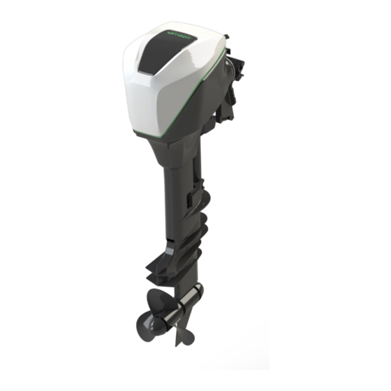
2. Product overview MotionPower10 is a 10kW electric outboard motor kit with tiller control and a LCD display. Both an electronic lever and the display are included in this kit. 2.1. Scope of delivery The complete set of Your MotionPower_10 system includes all of the components listed below: •... - Page 10 Motor cover Bracket clamp Drive shaft Anti-cavitation plate Anode (bottom side) Gearbox Propeller Figure 2. Drive unit overview.
-
Page 11: The Lcd Display
2.3. The LCD display Display Previous screen Next screen Figure 3. The LCD display. The drive set is equipped with a color LCD display with 5 buttons. 2.4. Power distribution unit The power distribution unit (PDU) is the main connector of all electrical systems on board. -
Page 12: The Battery System
Positive „+” terminals for battery, charger and inverter connections Negative „-” terminals for battery, charger and inverter connections Land grid, charger and communication terminals Figure 4. The PDU (power distibution unit). 2.5. The battery system Your battery system is composed of several (depending on the configuration) battery modules. - Page 13 The system will not start fully until the lever is in the neutral position. A warning icon will appear on the LCD screen. Figure 6. Drive-by-wire lever, single, top mount version. Manouvering Manouvering forward reverse Cruising forward Full forward Full reverse Figure 7.
-
Page 14: Technical Data
Figure 8. Operation of the key. Left: key OFF, right: key ON. 2.7. Technical data Model MotionPower10 Continuous input power 10 kW Rated voltage 48 V Weight 35 kg Shaft length 600 mm Control Lever Steering Left/right 45 Trim mechanism Manual, 4 step Tilt mechanism Manual, 60... - Page 15 Size of a single module 368 x 323 x 199 mm Rated voltage 51,2 V Single module weight 30 kg Nominal capacity 50 Ah / 2560 Wh Net capacity (including protection limits) 45 Ah / 2304 Wh Voltage range 49 – 54,5 V Nominal discharge power / current of a 5120 W / 100 A single module...
-
Page 16: Safety
3. Safety 3.1. Safety features Safety feature Function Magnetic kill switch Disconnects the energy supply immediately and disables the inverter operation. The propeller comes to a stop, the user is informed using the display screen icon. Disconnects the motor and inverter from the battery system, turns off the system into “stand-by”... -
Page 17: Battery System Safety Features
Internal failure Disconnects the battery and stops its operation. The user is informed using the display screen icon. The battery flashes red for around 30s. Contact Your local mPower representative. -
Page 18: General Safety Features And Notes
• Read the instructions carefully before You operate the system. mPower accepts no liability for damage caused by actions contrary to these instructions. Failing to comply can result in personal or material damage. Additional safety and warning instructions apply to certain activities. This information can be found in the relevant sections of this instructions. -
Page 19: Before Use
3.3. Before use • Your MotionPower system must be handled only by appropriately qualified personnel or vendors who have the necessary training, physical aptitude and necessary tooling. Comply with the relevant national regulations. • Your authorized boat builder, dealer, installation facility can provide training in the operation and safety provisions of the MotionPower system. - Page 20 DANGER ! Risk of death or physical injuries if the motor brakes away from the transom or motor holder. • Use only mounting bolts provided by mPower, • Operate the system after proving that the mounting is secure. WARNING ! Risk of moderate to severe physical injuries if electrical parts are damaged or uninsulated.
- Page 21 WARNING ! Risk of death or moderate to severe physical injuries – unmatched batteries. • Connect batteries of identical type (manufacturer, capacity, voltage, age) and state of charge. WARNING ! Risk of death or moderate to severe physical injuries – short circuit. •...
- Page 22 • Depending on the size of the boat and local regulations keep the safety equipment ready – anchor, paddle, means of communication, safety lines, life vests, • Before You start the trip inform Yourself about intended travel route, charging possibilities, weather and water conditions, •...
-
Page 23: Installation
• When using the tilting always use the tilt lock. 4. Installation DANGER ! Risk of death or physical injuries if the motor brakes away from the transom or motor holder. • Use only mounting bolts provided by mPower,... - Page 24 • Operate the system after proving that attachment points specified for mounting purpose are not loose. WARNING ! Risk of death or moderate to severe physical injuries – rotating components. • Switch off the system or put the lever to zero position when people are in immediate vicinity of the drive shaft or the propeller, •...
-
Page 25: Mounting The Outboard Motor
4.1. Mounting the outboard motor ADVICE Mounting height: If the mounting of the motor is too high cavitation tends to occur and reduces the propulsive power. If the mounting is too low the water resistance increases and reduces the efficiency. It is recommended to mount the motor so that the anti-cavitation plate is between the bottom of the boat and a max. - Page 26 From below From below Figure 9. Grip points of the drive unit. 3. Place the motor on the transom so that it is positioned so close to the center as possible. Tighten the transom clamp screws evenly and securely. Figure 10. Tightening the motor bracket clamp on the transom. 4.
- Page 27 Figure 11. The tilt lock. 5. Unlock the lifting clamp by lifting it up. Figure 12. Lifting clamp - ulock. 6. Grab the bottom of the motor cover and slowly pull the motor up. Lock the tilting mechanism by pulling the clamp up. You should hear a sound “click” of the blocking mechanism.
-
Page 28: Start-Up And Operation
Figure 13. Lifted motor. Figure 14. Lifting clamp lock. 5. Start-up and operation Please read the safety information (above section) carefully. This section will give You an overview of the system connection and main system components. LCD display Drive-by-wire lever Battery system –... -
Page 29: Start-Up Of The System
5.1. Start-up of the system For other battery or system configurations please contact Your local boat workshop or a certified mPower boat electrician. The start-up procedure actions are listed below: Make sure that the key is turned OFF, the charging cable is not attached to... -
Page 30: Display And The User Interface
Figure 17. Operation of the key. Left: key OFF, right: key ON. If no errors during the start-up occur the display turns on (mPower logo), performs the internal system scan and the main screen appears and the status “READY” is displayed. The system is ready and waiting for lever command. - Page 31 Drive power Battery setting system warning Reverse drive mode Battery system state of charge Drive system warning Remaining drive Overall system operating temperature time Figure 19. Main user's screen. The user can switch between various information screens using the navigation buttons. Next Previous screen...
- Page 32 Figure 21. Screen with motor rotational speed. If the magnetic kill switch is not closed (the magnetic key is not in its mounting position) the user is informed with a following information: Figure 22. Main screen after kill switch is not present. If the system cannot operate at start or killswitch event due to wrong lever position the user is informed with following screen:...
-
Page 33: Trim, Shallow Water Lever And Tilting
Figure 23. User information for nonzero lever position system activation. 5.3. Trim, shallow water lever and tilting WARNING ! Risk of death or moderate to severe physical injuries – rotating components. • Switch off the system when people are in immediate vicinity of the drive shaft or the propeller, •... -
Page 34: Trim Adjustment
5.3.1. Trim adjustment Adjusting the trim depends on many factors as boat hull design and weight distribution, onboard. Trim adjustment procedure: 1. Stop the engine, put the lever to neutral position and turn the key OFF. 2. Unlock the tilt lock by pressing it firmly down. Figure 24. - Page 35 Figure 26. Trim rod in the bracket. 6. Reposition the rod in the desired hole. To raise the bow move the rod away from the transom. To lower the bow move the trim toward the transom. 7. Lower the motor in reverse order then raising it. 8.
-
Page 36: Shallow Water Mode
5.3.2. Shallow water mode WARNING ! Risk of moderate physical injuries or equipment damage – difficult steering. • Run the boat at minimum speed when using the shallow water cruising system. The tilt lock mechanism is not active while working in the shallow water mode. - Page 37 Figure 29. Lifting clamp unlock. 4. Grab the bottom of the motor cover and slowly pull the motor up. 5. Engage the shallow water mechanism by pulling the lever up. Figure 30. Shallow water clamp release. 6. Lock the shallow water mechanism by pushing the clamp down. 7.
-
Page 38: Charging The Battery
Figure 31. Tilt lock engage. 5.4. Charging the battery Typically Your MotionPower system comes with a built-in, onboard charger. After completing Your trip You can connect the charging port of Your boat with a one phase outlet of the closest Marina supply post. DANGER ! Danger of fire or burns. - Page 39 WARNING ! Risk of moderate to severe physical injuries if electrical parts are damaged or uninsulated. • Do not undertake any repair works whatsoever on the MotionPower electrical system Yourself, • If You detect a fault or loose wiring turn the system off, do not touch metal components of the battery system, power distribution unit or wiring, •...
-
Page 40: Warning And Error Codes
Warning and error codes Below You will find warning and error code descriptions of common situations. Warning Description Actions message Lack of communication with at 1. Check battery front least one battery modules, button indication (if the Display icon, power derating. battery is “on”, Battery 2. - Page 41 temperature 2. Check the cooling High. pump impeller (service). Derating active to protect the motor. Temperature of one of the 1. Uncover the battery battery modules higher then compartment/battery Display icon, C. Power derating by 15%. modules, ventilate the Battery compartment.
- Page 42 Check engine icon, inverter warning Improper voltage or offset of Lever feedback off-limits. the lever, 50% power derating. Perform lever calibration Check engine procedure. If reocurring - icon, lever contact service. warning At least one of the battery Contact service. modules communicates state of Battery state health below 80%.
- Page 43 2. If step 1 did not help – contact service. Error code 4. After the inverter pre-charge 1. Check HV connections time the inverter voltage differs on batteries and PDU. If Precharge from the battery voltage. loose - tighten. failed 2.
-
Page 44: Care, Service And Maintenance Intervals
Expendable parts and lubricants will lose their effectiveness over time and through normal usage regardless of the warranty period. symbol indicates the check-up which You may carry out yourself. symbol indicates the check-up or work to be done by Your mPower representative. -
Page 45: Disposal And Environment
/ / Inspection inlet Inspection or Wire harness replacement if necessary Disposal and environment The mPower drives are manufactured in compliance with EC Directive 2002/96. This directive governs the disposal of electrical and electronic devices, with the aim of... -
Page 46: Disposal Of Batteries
Please therefore direct your waste equipment for separate collection in an environmentally-friendly way; to do so, contact your mPower representative or boat builder. For customers in other countries We recommend that the system is not discarded as normal household waste, but is disposed of via separate collection in an environmentally friendly way. -
Page 47: Ec Declaration Of Conformity
normal household waste, because this could allow entry to the environment of pollutants which have effects injurious to health on humans, animals, and plants, and which build up in the food chain and in the environment. In addition, valuable raw materials are lost in this way. - Page 48 Member States relating to the making available on the market of electrical equipment designed for use within certain voltage limits, • DIRECTIVE 2006/42/EC OF THE EUROPEAN PARLIAMENT AND OF THE COUNCIL OF 17 May 2006 on machinery, and amending Directive 95/16/EC (recast).
Need help?
Do you have a question about the MotionPower 10 and is the answer not in the manual?
Questions and answers