
Summary of Contents for Geo 2015 TS
- Page 1 MODEL 2015 TS User Manual English Deutsch Francais GEO Calibration Inc. 2190 Smithtown Avenue Ronkonkoma, NY 11779...
-
Page 2: Table Of Contents
REFERENCE STANDARD RECALIBRATION ....35 Control Probe / Reference Sensor ......................35 Unit Offset Calibration via PuTTY ......................37 Accessing the Device Manager ......................37 ENTERING MODEL 2015 TS OFFSETS ......38 Reading the COM Port ..........................38 Installing PuTTY ............................38 PuTTY Setup ..............................38 Connecting Through PuTTY ........................39 Reading Temperature and Humidity Offsets ..................39... - Page 3 DRAINING THE RESERVOIR ........................49 CONDENSATION IN THE CHAMBER ......................50 CHANGING THE CONTROL PROBE ......................51 GEO Calibration Inc 2190 Smithtown Avenue, Ronkonkoma, NY 11779, USA Tel.: +001 (631) 471 - 6157 ● Fax: +001 (631) 471 - 6158 support@geocalibration.com ● www.geocalibration.com...
-
Page 4: Introduction
INTRODUCTION MESSAGE FROM GEO CALIBRATION Thank you for purchasing the GEO Calibration Model 2015 TS humidity and temperature generator/ calibrator. We look forward to providing you the highest quality technical support as you become familiar with your new humidity and temperature calibrator. -
Page 5: Product Warranty
GEO Calibration authorized resellers shall extend this warranty on new and unused products to end- use customers only but have no authority to extend a greater or different warranty on behalf of GEO Calibration. Warranty support requires activation and registration at: https://www.geocalibration.com/register... -
Page 6: Unpacking Instructions
GEO representative should have reviewed this with you at time of purchase, if not, please contact our support team and they will size an Expansion Chamber accordingly. The Model 2015 TS allows for multiple types and sizes of hygrometers, for a complete list please contact us at support@geocalibration.com. -
Page 7: Standard Packing Check List
STANDARD PACKING CHECK LIST Within the Shipped Case Part Number Description 01-215-00-0000 Model 2015 TS Humidity Generator 01-200-11-0001 Desiccant Canister 01-200-36-0002 Reference Standard / Control Probe 01-200-36-0011 2 Part Desiccant Tool 01-200-01-0013 Desiccant Clamps 01-200-01-0035 2015 TS Accessories Kit 01-200-36-0013... - Page 8 STANDARD PACKING CHECK LIST Contents of GEO Accessories Box Part Number Description 6 Port Door Square with 6 Plugs 01-001-00-0017 01-001-66-0001 GEO Knobs (1 pack) 01-200-01-0036 GEO Bungs (7 pack) Calibration Documents Part Number Description NO REORDER Factory Calibration Report...
-
Page 9: Visual Item Check List
VISUAL ITEM CHECK LIST Listed below are standard contents included with the purchase of a new Model 2015 TS. Control Probe Humidity Generator Desiccant Canister GEO Calibration Pre-Filled with molecular sieve HC2-S HygroClip control probe (pre-installed) Model 2015 TS P/N: 01-200-36-0002... -
Page 10: Accessory Bag Contents
ACCESSORY BAG CONTENTS USB Cable Mains Power Cord Fill Syringe (A to A) P/N: 01-200-69-0001 P/N: 01-200-46-0001 P/N: 01-200-36-0006 P/N: 01-200-46-0002 4 AMP Fuse (2pack) 1 AMP Fuse (2pack) Banana Jack to Aligator Connectors Red and Black Cable P/N: 01-200-30-0001 P/N: 01-200-85-0001 P/N: 01-200-85-0002... - Page 11 ACCESSORY BOX CONTENTS 7 Piece Bung Kit Chamber Door 4 Piece GEO Knob Kit With plug set P/N: 01-200-01-0036 P/N: 01-001-66-0001 P/N: 01-001-00-0017 Clear Door P/N: 02-350-07-0005...
-
Page 12: Available Accessories
AVAILABLE ACCESSORIES Replacement Replacement Replacement Fill Syringe Control Sensor Desiccant HC2-S HygroClip control probe P/N: 01-200-36-0002 P/N: 01-200-36-0006 P/N: 01-200-11-0001 ISO 17025 System 971 Door Chilled Mirror Recalibration Door P/N: 01-001-00-0029 P/N: 01-001-00-0010 P/N: 01-999-99-0004 Silicone Drawer Door Expansion Chamber Adapter Variations (Regular and Slimline) 01-001-00-0026... - Page 13 AVAILABLE ACCESSORIES Humidity Generator Part Number Description 01-200-11-0001 Desiccant Canister 01-200-36-0002 Control Probe 01-200-01-0035 2015 TS Accessories Kit 01-200-08-0025 Chamber Insert for Air Circulation 01-200-01-0013 01-200-01-0013 Desiccant Desiccant Clamps 01-200-69-0001 USB A to A Cable 01-200-46-0001 US Spec Power Cord / Mains Cable...
- Page 14 01-001-00-0028 2 Port Door with Plugs 01-001-00-0029 2 Port 971 Door with Plugs 02-350-07-0005 Solid (No Ports) Clear Square Door 01-001-66-0001 GEO Door Knobs 01-001-00-0026 Sample Drawer Door Contact us for more door options. Expansion Chamber Usable Dimensions Part Number Description 7.67”...
- Page 15 AVAILABLE ACCESSORIES Grommets / Bungs M36 are for Standard Hygrometers PG36 are for Chilled Mirror Adapters Bung Size Port Size Part Number Type 0.000” 01-004-09-0001 0.000 3.175 0.125” 01-004-09-0002 01-004-09-0003 6.350 0.250” 0.375” 01-004-09-0004 9.525 31.00 1.22” 0.500” Regular 01-004-09-0005 12.700 01-004-09-0006 0.625”...
-
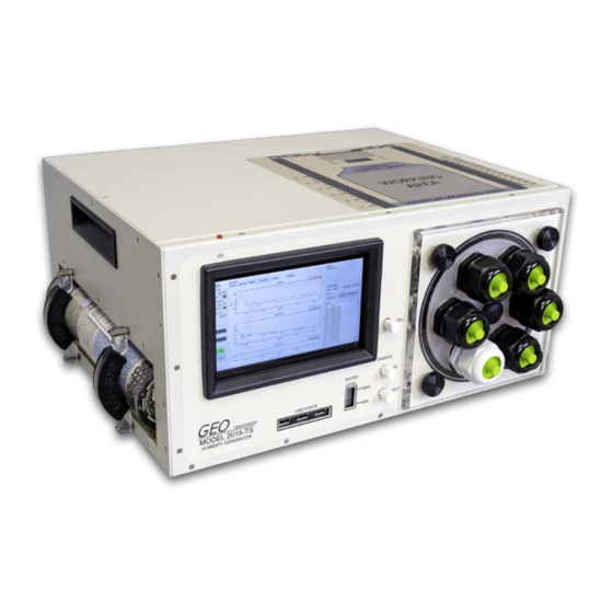
Page 16: Unit Diagram And Parts Listing
UNIT DIAGRAM AND PARTS LISTING Below you will find a diagram of the Model 2015 TS’s various operational parts. FRONT Fill Port Sample IN Depth Chart Display Desiccant Probe Port Port for Chilled Mirror Control Panel Door Screw Sample OUT... -
Page 17: Quick Start Guide
QUICK START GUIDE This guide is intended to give you the necessary information to quickly get up and running with your 2015 TS humidity and temperature generator. It includes the following instructions: • Filling the Reservoir • Powering On the Unit Unit Operation (Main Display) •... - Page 18 Read Before Turning On The Unit After receiving the unit, open the door to let the chamber dry for 10 minutes. Use soft paper tower to wipe the water in the chamber if needed. Turn on the unit and set the temperature to 30 °C and humidity to 30 % to let the unit settle, approximately for 20 minutes (first time only).
-
Page 19: Filling The Reservoir
FILLING THE RESERVOIR Supplies Needed Distilled Water Fill Syringe Only Locate the Fill Port The port is labeled and located on the middle lower portion of the front panel. Remove the Fill Cap Rotate Counter-Clockwise to remove. Attach Fill Syringe to Fill Port Press the fill syringe tip into the fill port, then rotate the cap clockwise to secure. - Page 20 Elevate and Fill Syringe - Pour distilled water into the elevated tube body. - Take care not to insert any air into the reservoir. - Monitor the water level indicator while filling. Loosen and Remove Syringe Turn the fill syringe tip counter-clockwise to loosen. Re-Install the Fill Cap Turn the cap clockwise to tighten the cap and seal the fill port.
-
Page 21: Powering The Unit
POWERING THE UNIT Supplies Needed Mains Power Cord Locate the Power Input Plug Power Supply into Wall Voltage range is 100 - 260 V AC - 50/60 Hz. Total power usage is 240 Watts. Plug Power Supply into Unit Set Power Switch to “ON”... -
Page 22: Unit Operation (Main Display)
UNIT OPERATION (MAIN DISPLAY) MAIN DISPLAY Figure 1 Main PC operational screen The Main screen of the GEO application is pictured above. The top area labeled Chamber Conditions shows the current environmental conditions in the chamber. The left values show the actual current readings, while the right values indicate the current set points. - Page 23 In the center area of the right portion of the screen in the area labeled is where the user may perform initial configuration of the GEO CIS-4.13, set up the ModBus and manage the experiments database. In bottom area of the righthand portion of the screen in the area labeled...
- Page 24 Figure 4 Experiments, Configuration and Console Experiments The GEO CIS software allows the user to create experiments. An experiment is defined by a se- quence of one or more phases each of which independently control the chamber conditions. The user may define any number of experiments and each may have any number of phases. Each experiment has a Title which is the displayed name of the experiment.
- Page 25 Figure 5 Experiment and Phase Definition Phase A phase defines the environmental conditions of the chamber for a period of time. Each phase has a naming convention, multiple phases may have the same naming. Optionally each phase may be logged independently to the experiment log into its own CSV file at its own data col- lection rate.
- Page 26 Modbus Initial setup The GEO CIS-4.13 uses the Modbus protocol over the USB/RS232 interface. First time the application is installed the communication port to which the unit is connected must be found. Configure’ button will cause the GEO-DFB If the system is powered on pressing the ‘Auto...
- Page 27 Plot control The plot area allows the user to control the scale range, line plot color and to zoom in and out of particular areas of interest. The screen that sets auto scaling and plot line color is shown below. To zoom the display to a particular area of interest the use should pause the plot updates by pressing the ‘Pause Plot’...
- Page 28 Figure 10 Zooming Graph for Humidity Figure 11 Zooming Graph for Dew Point...
- Page 29 Reports At any time the user may request a report to be printed on the currently collected informa- tion. To print a report, press the ‘Print Report’ button from the main screen. The user will be prompted for their Name, Title, Employee ID and any additional notes. The user must select a printer to which to send the report and select print when ready.
-
Page 30: Changing The Door / Opening The Chamber
CHANGING THE DOOR / OPENING THE CHAMBER Unscrew the Corner Screws Remove screws by turning in a counter-clockwise motion. Loosen Center Screw In some door variations, there is a center screw that serves the purpose of creating a tighter seal. If this screw exists, it must also be loosened using a counter-clockwise motion before the door can be removed. -
Page 31: General Specifications
GENERAL SPECIFICATIONS TRANSFER STANDARD No Charge CALIBRATION TO (17025 TRACEABLE TO NIST) 17025 Validation (Additional Fees Apply) CERTIFICATE TEMPERATURE 18 °C to 28 °C OPERATING AMBIENT CONDI- TIONS HUMIDITY Up to 80 % RH TEMPERATURE -20 °C to 50 °C STORAGE CONDITIONS 0 % to 95 % RH (non-condensing) HUMIDITY... -
Page 32: Consumables
CONSUMABLES RESERVOIR 200 ml SPILL RESISTANT WATER REQUIRED FLUID Distilled Water Only 15 Days to 1 Month (Typical) *Depends on Usage EST. REFILL PERIOD FILL INDICATOR Floating Ball TYPE Molecular Sieve When Indicating Desiccant is 3/4 Used REPLACEMENT DESICCANT REPLACEMENT FREQUENCY Depends Entirely on User Workload LOCATION Left Side Mounted... -
Page 33: Calibration
Ensure the door is securely fastened to the chamber. Insert UUT Insert your UUT at least 3 inches into the Model 2015 TS chamber. Program Unit Set-points Allow the unit to reach the programmed set-points and settle. -
Page 34: System Recalibration
• Uniformity – Mixing of the humidity and temperature inside the chamber can cause uniformity issues. GEO has a unique chamber design to achieve high uniformity within all GEO chambers. • Sensor/Probe Uncertainty – This is the largest contributor to system uncertainty and that is why system probes are calibrated using instruments and standards traceable to the National Institute of Standards and Technology (NIST). -
Page 35: Reference Standard Recalibration
Control Probe / Reference Sensor Overview The Model 2015 TS functions through the use of a dual PID controller. This controller takes the humid- ity and temperature values from an internal capacitance probe and further performs calculations that are then used to generate the user entered humidity and temperature set points. This sensor is factory calibrated, and upon request, additionally calibrated by an ISO 17025 accredited laboratory using either a chilled mirror or two-pressure primary reference standard. - Page 36 REFERENCE STANDARD RECALIBRATION Self Recalibration Procedure To read the recalibration procedure of the control / reference probe, please refer to the unit’s user manual, and the HW4 software manual found at the following URLs as of publication of this manual: https://s.campbellsci.com/documents/ca/manuals/hc2-s3-l_man.pdf https://goo.gl/n7qE1G https://www.instrumart.com/assets/rotronic-hygroclip2-probes-manual.pdf...
-
Page 37: Unit Offset Calibration Via Putty
USB Port Unit Offset Calibration via PuTTY The Model 2015 TS also allows users to make two, single point adjustments for both temperature and humidity. It is recommended that users recalibrate their unit as needed to fit their overall uncer- tainty requirements. -
Page 38: Entering Model 2015 Ts Offsets
ENTERING MODEL 2015 TS OFFSETS Reading the COM Port At this time, plug the unit’s power supply into an approved power source. Plug the USB mouse and keyboard into the Unit. Toggle both the power switches to the “ON” position. -
Page 39: Connecting Through Putty
ENTERING MODEL 2015 TS OFFSETS Connecting Through PuTTY In PuTTY, select Session menu under Category on the left Input your COM Port (reference Reading the Serial Port instruction from above) into the Serial line field Under Connection type, select Serial... -
Page 40: Changing Humidity And Temperature Offsets
ENTERING MODEL 2015 TS OFFSETS Changing Humidity and Temperature Offsets PLEASE NOTE: #.# is a placeholder In the following instructions, replace # with your desired integers. (For example, #.# would become 1.2 or -0.2) Temperature: type TOFFSET #.# and press the Enter key. The unit will query and display the tem- perature offset. -
Page 41: Safety Warning
● Disruption of the ground could put voltage on the chassis that could cause death. ● Use the Model 2015 TS only as specified, or the protection supplied by the Product can be compromised. ● Do not put the Model 2015 TS where access to the power cord isn’t possible. -
Page 42: Disposal Safety Information
TECHNICAL SUPPORT Locations GEO Calibration Inc 2190 Smithtown Avenue, Ronkonkoma, NY 11779, USA Tel.: +001 (631) 471 - 6157 ● Fax: +001 (631) 471 - 6158 support@geocalibration.com ● www.geocalibration.com © GEO Calibration Inc. 2020... -
Page 43: Repairs
Have the Product information ready such as the purchase date and serial number to schedule the repair ● Ship the unit to GEO in the original shipping container or one designed specifically for “Safe Travel” ● Apply your RMA # on the outside of the shipping package in large numbers ●... -
Page 44: Maintenance
MAINTENANCE SERVICE SCHEDULE ● Maintenance Recommendations: GEO Calibration recommends that the unit be annually shipped back to our facility for general maintenance. Daily Semi-Annual As Needed General Cleaning Refill Reservoir with Distilled (Use Proper Cleaning Control Probe Calibration Water Materials) -
Page 45: Desiccant Change Visual Guide
DESICCANT CHANGE VISUAL GUIDE Overview The Model 2015 TS ships with a fresh desiccant canister. Each time the Model 2015 TS dries the internal volume of air, the desiccant will become more saturated with water. For optimal performance, the user must periodically replenish or replace the used desiccant. The desiccant type is molecular sieve, which may be regenerated by the user through heating or baking. -
Page 46: Replacing The Canister
REPLACING THE CANISTER Power Off the Unit Ensure that the unit is powered off before proceeding with a desiccant change. Loosen Hook & Loop Straps Firmly Grasp Desiccant This will cause the old desiccant canister to slide from the female adapters. Remove this desiccant completely from the housing and set aside. - Page 47 Firmly Insert Desiccant Canister Ensure the hose barbs properly line up with the sockets on the inside of the desiccant housing. Press with Force Firmly press the seal with both thumbs into the canister housing. Secure Hook & Loop Straps...
-
Page 48: Refilling Desiccant Canister
REFILLING DESICCANT CANISTER Remove Desiccant Follow the initial steps from the previous section entitled “Desiccant Change”. Open Top Cover of Desiccant Save the spring, the sieve and the three white felt filters. Discard previous desiccant. Wipe the inside of the desiccant cannister with a clean cloth. -
Page 49: Draining The Reservoir
DRAINING THE RESERVOIR Locate the Main Drain Port Turn the cap counter-clockwise to remove. Move the Unit to Table Edge Position a bowl shaped object underneath the unit to catch the drained water. Remove the Drain Cap Tilt the unit to ensure maximum water removal. Replace &... -
Page 50: Condensation In The Chamber
CONDENSATION IN THE CHAMBER Power Off the Unit Ensure that the unit is powered off. This is so that no desiccant is wasted while the unit is not in operation. Open the Chamber Door Follow the door opening procedure from the quick start guide. -
Page 51: Changing The Control Probe
CHANGING THE CONTROL PROBE Open Chamber Door Turn the screws counter-clockwise to loosen. Remove the door. Remove Chamber Insert Loosen Metal Connector Twist towards the chamber opening to loosen. Remove Probe Head... - Page 52 Locate Probe Connector Press Probe into Connector Slowly rotate the probe head as you press into the cabling body. You will feel the probe “seat” itself once the male - female parts align. Secure Metal Connector Twist the metal connector away from the chamber entrance to secure the probe head to the probe cabling body.
- Page 53 INDUSTRIES PHARMACEUTICAL MANUFACTURING CALIBRATION LABS BIOMEDICAL R&D FACILITIES FOOD PRODUCTION AUTOMOTIVE MANUFACTURING AEROSPACE HOSPITAL / MEDICAL CLEAN ROOMS For a complete product and accessory review, please visit our website: www.geocalibration.com CONTACT US: Email: Sales@GeoCalibration.com Sales@GeoCalibration. Website: www.GeoCalibration.com www.GeoCalibration. (631) 471 - 6157...
- Page 54 Proudly Made in the USA Email: Sales@GeoCalibration.com Website: www.GeoCalibration.com © 2020 GEO Calibration Inc. All rights reserved. Rev A...
Need help?
Do you have a question about the 2015 TS and is the answer not in the manual?
Questions and answers