Table of Contents
Advertisement
Available languages
Available languages
Quick Links
Schnittstelle für digitale Stromzähler
Interface for digital electricity meters
HmIP-ESI-LED
Installations- und
DE
Bedienungsanleitung
Installation and operating
EN
manual
Notice d'installation et
FR
d'emploi
Manual de instalación
ES
y uso
Istruzioni per l'installazione
IT
e l'uso
Installatie- en
NL
bedieningshandleiding
Advertisement
Chapters
Table of Contents

Subscribe to Our Youtube Channel
Related Manuals for Homematic IP HmIP-ESI-LED


Summary of Contents for Homematic IP HmIP-ESI-LED
- Page 1 Schnittstelle für digitale Stromzähler Interface for digital electricity meters HmIP-ESI-LED Installations- und Manual de instalación Bedienungsanleitung y uso Installation and operating Istruzioni per l‘installazione manual e l‘uso Notice d‘installation et Installatie- en d‘emploi bedieningshandleiding...
-
Page 2: Table Of Contents
Installations- und Bedienungsanleitung Inhaltsverzeichnis Lieferumfang ....................3 Hinweise zur Anleitung ................3 Gefahrenhinweise ..................3 Funktion und Geräteübersicht ..............4 Allgemeine Systeminformationen .............5 Inbetriebnahme .....................5 Anlernen ....................... 5 Montage ........................ 6 6.2.1 Klebestreifenmontage ................6 6.2.2 Schraubmontage ................... 7 6.2.3 Sensormontage ..................7 Batterien wechseln ..................8 Fehlerbehebung ....................9 Schwache Batterien .................... -
Page 3: Lieferumfang
Lieferumfang Lieferumfang Aus Sicherheits- und Zulassungs- gründen (CE) ist das eigenmächti- 1x Homematic IP Schnittstelle für ge Umbauen und/oder Verändern Energiesensor des Gerätes nicht gestattet. 1x Energiesensor LED Betreiben Sie das Gerät nur in 2x Doppelseitige Klebestreifen trockener sowie staubfreier Um- 2x 1,5 V LR6/Mignon/AA Batterie gebung. -
Page 4: Funktion Und Geräteübersicht
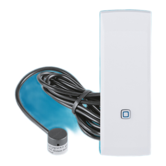
Funktion und Geräteübersicht 4 Funktion und Geräteübersicht Die Homematic IP Schnittstelle für Energiesensoren ist ein batteriever- sorgtes Funkmodul zum Einbinden von Energiezählern in Homematic IP Ins- tallationen. Sie dient zur Erfassung der Energiedaten von Stromzählern. Der Energiesensor LED erfasst im sicht- baren Lichtspektrum blinkende LEDs ebenso, wie Infrarot-LEDs. -
Page 5: Allgemeine Systeminformationen
Allgemeine Systeminformationen 5 Allgemeine Damit das Gerät in Ihr System integriert Systeminformationen werden und mit anderen Homematic IP Geräten kommunizieren kann, muss es Dieses Gerät ist Teil des Homematic IP zunächst an den Homematic IP Access Smart-Home-Systems und kommuni- Point angelernt werden. ziert über das Homematic IP Funkpro- Zum Anlernen gehen Sie wie folgt vor: tokoll. -
Page 6: Montage
Inbetriebnahme Sie können den Anlernmodus (als Offset) erfassen, um künftig manuell für weitere 3 Minuten einen Gesamtzählerstand anzei- starten, indem Sie die Systemtaste gen zu können. Diese Einstellung (A) kurz drücken. finden Sie in den Geräteeinstel- lungen der Schnittstelle. Öffnen Sie dafür die Homematic IP App, tippen Sie auf „Mehr...“... -
Page 7: Schraubmontage
Inbetriebnahme Der Abstand zwischen Unterseite vom Schraubenkopf und Monta- gefläche sollte ungefähr 2 mm be- tragen. • Fädeln Sie den Schraubkanal (C) auf der Rückseite über den Schrau- benkopf. • Drücken Sie das Gerät rückseitig an die gewünschte Position. • Setzen Sie die Abdeckkappe (B) auf, bis sie vollständig eingerastet ist. - Page 8 Inbetriebnahme • Markieren Sie bei Bedarf die Mon- tageposition mit Hilfe der beilie- genden Schablone, um die mittige Ausrichtung vor der Impuls-LED zu gewährleisten. • Stecken Sie abschließend den Steckverbinder (H) des Sensors an der Unterseite des HmIP-ESI in die Anschlussbuchse (E), bis dieser hörbar einrastet.
-
Page 9: Batterien Wechseln
Batterien wechseln der anderen Hand auf der Rück- seite des HmIP-ESI die Rippe der Elektronikeinheit (G) und ziehen Sie diese aus der Abdeckung heraus (siehe Abbildung). • Entnehmen Sie die leeren Batteri- • Legen Sie zwei neue 1,5 V LR6/Mi- gnon/AA Batterien entsprechend der Polaritätsmarkierungen in das Batterien wechseln... -
Page 10: Fehlerbehebung
Fehlerbehebung 8.2 Duty Cycle Nach dem Einlegen der Batterien führt das Gerät zunächst für ca. 2 Sekunden Der Duty Cycle beschreibt eine ge- einen Selbsttest durch. Danach erfolgt setzlich geregelte Begrenzung der die Initialisierung. Den Abschluss bildet Sendezeit von Geräten im 868 MHz die Test-Anzeige: oranges und grünes Bereich. -
Page 11: Fehlercodes Und Blinkfolgen
Fehlerbehebung 8.3 Fehlercodes und Blinkfolgen Blinkcode Bedeutung Lösung Funkübertragung/Sen- Warten Sie, bis die Über- Kurzes oranges Blinken deversuch/Datenüber- tragung beendet ist. tragung 1x langes grünes Vorgang Sie können mit der Bedie- Leuchten bestätigt nung fortfahren. Vorgang fehlgeschlagen Versuchen Sie es erneut 1x langes rotes Leuchten oder Duty Cycle-Limit (s. -
Page 12: Wiederherstellung Der Werkseinstellungen
Wiederherstellung der Werkseinstellungen 9 Wiederherstellung der Werkseinstellungen Die Werkseinstellungen des Ge- räts können wiederhergestellt werden. Dabei gehen alle Einstel- lungen verloren. Um die Werkseinstellungen des Geräts wiederherzustellen, gehen Sie wie folgt vor: • Im montierten Zustand lässt sich • Lassen Sie die Systemtaste (A) wie- der Abdeckkappe (B) einfach vom der los, um das Wiederherstellen montierten Gerät lösen, indem Sie... -
Page 13: Allgemeine Hinweise Zum Funkbetrieb
Allgemeine Hinweise zum Funkbetrieb 11 Allgemeine Hinweise zum für Elektro- und Elektronik-Altgeräte Funkbetrieb bzw. für Altbatterien abzugeben. Auch Vertreiber von Elektro- und Elektronik- Die Funk-Übertragung wird auf einem geräten bzw. Batterien sind zur unent- nicht exklusiven Übertragungsweg re- geltlichen Rücknahme von Altgeräten alisiert, weshalb Störungen nicht aus- bzw. -
Page 14: Technische Daten
Technische Daten 13 Technische Daten 13.1 Technische Daten HmIP-ESI Geräte-Kurzbezeichnung: HmIP-ESI Versorgungsspannung: 2x 1,5 V LR6/Mignon/AA Stromaufnahme: max. 30 mA Batterielebensdauer: 5 Jahre (typ. mit ES-LED) Schutzart: IP20 Umgebungstemperatur: 5 bis 35 °C Abmessungen (B x H x T): 39 x 109 x 29 mm Gewicht: 100 g (inkl. - Page 15 Installation and operating manual Table of contents Scope of delivery ..................16 Information about this manual ..............16 Hazard information ..................16 Function and device overview ..............17 General system information ..............18 Start-up ......................18 Pairing ......................... 18 Installation ......................19 6.2.1 Adhesive strip mounting ..............19 6.2.2 Screw mounting ...................20 6.2.3 Mounting the sensor ................20 Changing the batteries ................21...
-
Page 16: Scope Of Delivery
Scope of delivery Scope of delivery For safety and licensing reasons (CE), unauthorized change and/or 1x Homematic IP interface for ener- modification of the device is not gy sensors permitted. 1x LED energy sensor The device may only be operated 2x Double-sided adhesive strips in dry and dust-free environment. -
Page 17: Function And Device Overview
Function and device overview 4 Function and device overview The Homematic IP interface for energy sensors is a battery-powered wireless module for integrating energy me- ters into Homematic IP installations. It is used for acquiring the energy data from electricity meters. The LED energy sensor detects LEDs flashing in the visible light spectrum as well as infra-red LEDs. -
Page 18: General System Information
General system information 5 General system information For pairing, proceed as follows: • Open the Homematic IP app on This device is a part of the your smart phone. Homematic IP Smart Home system and • Select the menu item “Add device”. communicates via the Homematic IP •... -
Page 19: Installation
Start-up 6.2 Installation You can use either • the supplied double-sided adhesive strips or • a screw (not included in the deliv- ery) to affix the HmIP-ESI in the chosen position. Make sure that the mounting lo- cation does not affect the wireless Your device will automatically appear communication between the in the Homematic IP app. -
Page 20: Screw Mounting
Start-up 6.2.2 Screw mounting 6.2.3 Mounting the sensor When selecting the installation To mount the sensor, proceed as fol- location, check for electrical wires lows: and power supply cables. • Clean the area around the pulse LED on the meter. The surface A round headed screw with a 3 must be undamaged, clean, free mm diameter is to be used for... -
Page 21: Changing The Batteries
Changing the batteries • Affix the reader head in front of the pulse LED and press down on it firmly for 5 seconds. Changing the batteries If an empty battery is displayed in the app or on the device (see „8.3 Error codes and flashing sequences“... -
Page 22: Troubleshooting
Troubleshooting with your other hand and pull it out of the cover (see illustration). Once the batteries have been inserted, the device will perform a self-test for • Remove the used batteries. approx. 2 seconds. Afterwards, ini- tialisation is carried out. The LED test display will indicate that initialisation is complete by lighting up orange and green. -
Page 23: Duty Cycle
Troubleshooting 8.2 Duty cycle The duty cycle is a legally regulated limit of the transmission time of de- vices in the 868 MHz range. The aim of this regulation is to safeguard the operation of all devices working in the 868 MHz range. -
Page 24: Error Codes And Flashing Sequences
Troubleshooting 8.3 Error codes and flashing sequences Flashing code Meaning Solution Radio transmission/send Wait until the transmis- Short orange flashes attempt/data transmis- sion is completed. sion You can continue opera- 1x long green lighting Transmission confirmed tion. Try again Transmission failed or 1x long red flash (see „8.2 Duty cycle“... -
Page 25: Restoring Factory Settings
Restoring factory settings 9 Restoring factory settings The device’s factory settings can be restored. If you do this, you will lose all your settings. To restore the factory settings of the device, please proceed as follows: • When mounted, the cover (B) can be easily removed from the mount- ed device by pressing in the upper and lower sides and pulling the... -
Page 26: General Information About Radio Operation
General information about radio operation 11 General information about electrical and electronic equipment to radio operation ensure their correct disposal. Distribu- tors of electrical and electronic equip- Radio transmission is performed on ment or batteries must also take back a non-exclusive transmission path, obsolete equipment or batteries free of which means that there is a possibility charge. -
Page 27: Technical Specifications
Technical specifications 13 Technical specifications 13.1 HmIP-ESI technical data Device short description: HmIP-ESI Supply voltage: 2x 1.5 V LR6/Mignon/AA Current consumption: max. 30 mA Battery life: 5 years (typical, with ES-LED) Protection rating: IP20 Ambient temperature: 5 to 35°C Dimensions (W x H x D): 39 x 109 x 29 mm Weight: 100 g (including batteries) - Page 28 Notice d‘installation et d‘emploi Table des matières Contenu de la livraison ................29 Remarques sur la notice ................29 Mises en garde .................... 29 Fonction et aperçu de l’appareil ............. 30 Informations générales sur le système ..........30 Mise en service ....................31 Apprentissage ....................
-
Page 29: Contenu De La Livraison
Contenu de la livraison Contenu de la livraison Notre responsabilité ne saurait être engagée en cas de dom- 1x Interface Homematic IP pour mages matériels ou de dommages capteur d’énergie corporels dus au maniement inap- 1x Capteur d’énergie LED proprié ou au non-respect des 2x Bande adhésive double face mises en garde. -
Page 30: Fonction Et Aperçu De L'appareil
Fonction et aperçu de l’appareil 4 Fonction et aperçu de l’appareil L’interface Homematic IP pour cap- teurs d’énergie est un module radio alimenté par piles permettant d’inté- grer des compteurs énergétiques dans des installations Homematic IP. Elle sert à relever les données énergétiques issues de compteurs électriques. -
Page 31: Informations Générales Sur Le Système
Informations générales sur le système 5 Informations générales sur Afin que l’appareil puisse être intégré le système à votre système et communiquer avec d’autres appareils Homematic IP, Cet appareil fait partie du système vous devez d’abord procéder à son Smart Home Homematic IP et com- apprentissage avec l’Homematic IP munique via le protocole radio Home- Access Point. -
Page 32: Montage
Mise en service Vous pouvez lancer manuelle- indication sur votre compteur. En ment le mode d’apprentissage outre, vous devez saisir la valeur pendant 3 minutes supplémen- actuelle du compteur (en tant taires en appuyant brièvement sur qu’offset) pour pouvoir afficher à la touche système (A). -
Page 33: Montage Par Vis
Mise en service • Enfilez le canal de vissage (C) à l’ar- rière sur la tête de la vis. Appuyez sur l’appareil pour le coller avec le dos sur la position souhaitée. • Installez le cache (B) de sorte qu’il •... - Page 34 Mise en service • Nettoyez la surface du compteur dans la zone de la LED d’impulsion. La surface doit être intacte, propre, exempte de graisse et de solvant et pas trop froide, afin que le capteur puisse adhérer à long terme. •...
-
Page 35: Remplacement Des Piles
Remplacement des piles l’arrière du HmIP-ESI et retirez-le du cache (voir figure). • Enlevez les piles usagées. • Insérez deux piles neuves de 1,5 V LR6/Mignon/AA dans le compar- timent à piles (F) en respectant les repères de polarité. Remplacement des piles Si l’application ou l’appareil affiche une pile vide (v. -
Page 36: Dépannage
Dépannage 8.2 Duty Cycle suite. L’affichage de test constitue la fin : éclairage orange et vert. Le Duty Cycle décrit une limite légale Attention ! Risque d’explosion en réglée de la durée d’émission des ap- cas de remplacement inapproprié pareils dans la bande de fréquence des piles. -
Page 37: Codes D'erreur Et Séquences De Clignotement
Dépannage 8.3 Codes d’erreur et séquences de clignotement Code de clignotement Signification Solution Transmission radio/Ten- Attendez que la transmis- Bref clignotement orange tative d’émission/Trans- sion soit terminée. mission de données Vous pouvez poursuivre 1 long éclairage vert Processus confirmé avec la commande. Essayez à... -
Page 38: Restauration Des Paramètres D'usine
Restauration des paramètres d’usine 9 Restauration des paramètres d’usine Les réglages d’usine de l’appareil peuvent être rétablis. Dans ce cadre, tous les réglages antérieurs sont perdus. Afin de rétablir les réglages d’usine de l’appareil, procédez comme suit : • Une fois monté, le cache (B) peut être détaché... -
Page 39: Remarques Générales Sur Le Fonctionnement Radio
Remarques générales sur le fonctionnement radio 11 Remarques générales sur le à un centre de collecte communal fonctionnement radio pour appareils électriques et électro- niques ou piles usagé(e)s en vue d’un La transmission radio est réalisée sur recyclage approprié. Les distributeurs une voie de transmission non exclu- d’appareils électriques et électroniques sive, c’est pourquoi des dysfonction-... -
Page 40: Caractéristiques Techniques
Caractéristiques techniques 13 Caractéristiques techniques 13.1 Caractéristiques techniques HmIP-ESI Désignation abrégée de l’appareil : HmIP-ESI Tension d’alimentation : 2x 1,5 V LR6/Mignon/AA Courant absorbé : max. 30 mA Durée de vie des piles : 5 ans (typ. avec ES-LED) Type de protection : IP20 Température ambiante : 5 à 35 °C Dimensions (l x H x P) : 39 x 109 x 29 mm Poids :... - Page 41 Manual de instalación y uso Índice Volumen de suministro ................42 Advertencias sobre estas instrucciones ..........42 Advertencias de peligro ................42 Funciones y esquema del dispositivo ............. 43 Información general del sistema ............44 Puesta en servicio ..................44 Conexión ......................44 Montaje .......................
-
Page 42: Volumen De Suministro
Volumen de suministro Volumen de suministro Se declina toda responsabilidad por las lesiones o los daños mate- 1x Interfaz Homematic IP para sen- riales causados por un uso indebi- sor de energía do o incumplimiento de las adver- 1x Sensor de energía LED tencias de peligro. -
Page 43: Funciones Y Esquema Del Dispositivo
Funciones y esquema del dispositivo 4 Funciones y esquema del dispositivo La interfaz Homematic IP para senso- res de energía es un módulo inalám- brico alimentado con pilas para la in- tegración de contadores de energía en instalaciones Homematic IP. Sirve para registrar los datos de energía de conta- dores eléctricos. -
Page 44: Información General Del Sistema
Homematic IP Access Point. Este dispositivo forma parte del sis- Modo de proceder para conectar el tema Homematic IP Smart Home y dispositivo: se comunica mediante el protocolo • Abra la app Homematic IP en su inalámbrico Homematic IP. Todos los móvil. -
Page 45: Montaje
Puesta en servicio un valor total del contador en el futuro. Este ajuste se encuentra en los ajustes de la interfaz. Para ello, abra la app Homematic IP, pulse en «Más...» y seleccione el dispo- sitivo en la vista general de dispo- sitivos. -
Page 46: Montaje Con Tornillos
Puesta en servicio • Pase el canal de tornillo (C) de la parte trasera sobre el cabezal del tornillo. • Presione el dispositivo por la parte trasera sobre el lugar deseado. • Coloque la tapa (B) de modo que quede completamente encajada. •... - Page 47 Puesta en servicio • En caso necesario, marque la posi- ción de montaje mediante la plan- tilla adjunta para asegurarse de que el LED de impulsos quede centra- • Por último, introduzca el conector (H) del sensor en la parte inferi- or de la HmIP-ESI, en la toma de conexión (E), hasta que encaje de forma audible.
-
Page 48: Cambio De Pilas
Cambio de pilas unidad electrónica (G), en la parte trasera de la HmIP-ESI, y tire de ella para sacarla de la tapa (v. figura). • Extraiga las pilas vacías. Introduzca dos pilas nuevas LR6/Mig- non/AA de 1,5 V en la posición correcta según las marcas grabadas (F). -
Page 49: Reparación De Fallos
Reparación de fallos 8.2 Duty Cycle Tras la colocación de las pilas el dis- positivo ejecuta en primer lugar una Duty Cycle describe una limitación del prueba automática durante unos 2 tiempo de transmisión regulada por ley segundos. A continuación tiene lugar para dispositivos en la banda de 868 la inicialización. -
Page 50: Códigos De Errores Y Secuencias Intermitentes
Reparación de fallos 8.3 Códigos de errores y secuencias intermitentes Secuencia intermitente Significado Solución Transmisión inalámbrica, Luz naranja intermitente Espere hasta que finalice intento de transmisión o corta la transmisión. transmisión de datos 1 vez luz verde Confirmación de Puede continuar con el larga una operación manejo. -
Page 51: Restablecimiento De La Configuración De Fábrica
Restablecimiento de la configuración de fábrica 9 Restablecimiento de la configuración de fábrica Se puede restablecer la configu- ración de fábrica del dispositivo. Al hacerlo se pierden todos los ajustes. Modo de proceder para restablecer la configuración de fábrica del dispositi- •... -
Page 52: Indicaciones Generales Sobre El Modo Inalámbrico
Indicaciones generales sobre el modo inalámbrico 11 Indicaciones generales suministro y las pilas para su correcta sobre el modo inalámbrico eliminación en un punto de recogida de residuos municipal para aparatos La transmisión inalámbrica se realiza eléctricos y electrónicos usados o para por una vía de transmisión no exclu- pilas usadas. -
Page 53: Datos Técnicos
Datos técnicos 13 Datos técnicos 13.1 Datos técnicos de la HmIP-ESI Nombre abreviado del dispositivo: HmIP-ESI Tensión de alimentación: 2 pilas LR6/Mignon/AA, 1,5 V Consumo de corriente: máx. 30 mA Duración de las pilas: 5 años (típ. con ES-LED) Tipo de protección: IP20 Temperatura ambiente: de 5 a 35 °C... - Page 54 Istruzioni per l‘installazione e l‘uso Indice Fornitura .......................55 Indicazioni su queste istruzioni ..............55 Indicazioni di pericolo................55 Funzioni e vista d’insieme dell’apparecchio Informazioni generali sul sistema ............57 Messa in funzione ..................57 Inizializzazione ....................57 Montaggio ......................58 6.2.1 Montaggio con strisce adesive............58 6.2.2 Montaggio con viti ................59 6.2.3 Montaggio del sensore ..............
-
Page 55: Fornitura
Fornitura Fornitura Per ragioni di sicurezza o di omo- logazione (CE) non sono ammesse 1x Interfaccia Homematic IP per modifiche costruttive o di altro sensore di energia genere dell’apparecchio. 1x Sensore di energia LED Utilizzare l’apparecchio solo in 2x Strisce bi-adesive ambienti asciutti e privi di polvere. -
Page 56: Funzioni E Vista D'insieme Dell'apparecchio
Funzioni e vista d’insieme dell’apparecchio 4 Funzioni e vista d’insieme dell’apparecchio L’interfaccia Homematic IP per sensori di energia è un modulo radio a batteria per integrare contatori di energia negli impianti Homematic IP. Essa serve a rilevare dati energetici dei contatori di corrente. -
Page 57: Informazioni Generali Sul Sistema
Questo apparecchio fa parte del si- Homematic IP, occorre prima stema Homematic IP Smart-Home e inizializzarlo sull’Access Point comunica tramite il protocollo radio Homematic IP. Homematic IP. Tutti gli apparecchi Per eseguire l’inizializzazione procede-... -
Page 58: Montaggio
Messa in funzione La modalità Inizializzazione può tore stesso. Inoltre è necessario essere avviata per altri 3 minuti rilevare lo stato effettivo del con- premendo brevemente il tasto di tatore (come offset) per poter sistema (A). visualizzare in futuro uno stato complessivo del contatore. -
Page 59: Montaggio Con Viti
Messa in funzione • Inserire il canale a vite (C) sul lato posteriore attraverso la testa della vite. • Premere il retro dell’apparecchio nella posizione desiderata. • Applicare il coperchio protettivo (B) fino all’arresto completo. • Applicare il coperchio protettivo 6.2.2 Montaggio con viti (B) sull’unità... -
Page 60: Montaggio Del Sensore
Messa in funzione 6.2.3 Montaggio del sensore • Incollare la testina di lettura a monte del LED di impulso e tenerla Per montare il sensore, procedere premuta per 5 secondi. come descritto di seguito: • Pulire la superficie del contatore nella zona del LED di impulso. -
Page 61: Sostituzione Delle Batterie
Sostituzione delle batterie l’altra mano la nervatura dell’unità elettronica (G) sul lato posteriore dell’HmIP-ESI e rimuoverla dalla copertura (v. figura). • Rimuovere le batterie scariche. • Inserire due nuove batterie LR6/ Mignon/AA da 1,5 V rispettando la polarità come indicato nel vano batterie (F). -
Page 62: Risoluzione Dei Guasti
Risoluzione dei guasti Dopo aver inserito le batterie, l’appa- nuove (v. “7 Sostituzione delle batterie“ recchio esegue innanzitutto un test a pag. 61). autodiagnostico per ca. 2 secondi. Su- bito dopo esegue l’inizializzazione. La 8.2 Duty Cycle visualizzazione del test rappresenta la Il Duty Cycle descrive una limitazione conclusione: luce arancione e verde. -
Page 63: Codici Di Errore E Sequenze Di Spie Lampeggianti
Risoluzione dei guasti 8.3 Codici di errore e sequenze di spie lampeggianti Codice di segnalazione Significato Soluzione Trasmissione radio/tenta- Luce arancione lampeg- Attendere che la trasmis- tivo di invio/trasmissione giante per breve tempo sione sia conclusa. dati Luce verde accesa Procedura Si può... -
Page 64: Ripristino Delle Impostazioni Di Fabbrica
Ripristino delle impostazioni di fabbrica 9 Ripristino delle impostazioni di fabbrica L’utente può ripristinare le impo- stazioni di fabbrica dell’apparec- chio. In questo caso tutte le im- postazioni andranno perdute. Per ripristinare le impostazioni di fab- brica dell’apparecchio procedere nel modo seguente: •... -
Page 65: Informazioni Generali Sul Funzionamento Via Radio
Informazioni generali sul funzionamento via radio 11 Informazioni generali sul centro di raccolta comunale per ap- funzionamento via radio parecchi elettrici ed elettronici usati o batterie esauste. Anche i distributori di La trasmissione radio viene attuata su apparecchi elettrici ed elettronici o di un canale di trasmissione non esclu- batterie sono tenuti a ritirare gli appa- sivo, pertanto non è... -
Page 66: Dati Tecnici
Dati Tecnici 13 Dati Tecnici 13.1 Dati tecnici HmIP-ESI Sigla dell’apparecchio: HmIP-ESI Tensione di alimentazione: 2 batterie LR6/mignon/AA da 1,5 V Corrente assorbita: max. 30 mA Durata batterie: 5 anni (tip. con ES-LED) Grado di protezione: IP20 Temperatura ambiente: tra 5 e 35 °C Dimensioni (L x A x P): 39 x 109 x 29 mm Peso:... - Page 67 Installatie- en bedieningshandleiding Inhoudsopgave Leveringsomvang ..................68 Instructies bij deze handleiding .............. 68 Veiligheidsinformatie ................. 68 Werking en overzicht van het apparaat ..........69 Algemene systeeminformatie ..............70 Inbedrijfstelling ....................70 Inleren ......................... 70 Montage .......................71 6.2.1 Montage met plakstrips ..............71 6.2.2 Montage met schroeven ..............
-
Page 68: Leveringsomvang
Leveringsomvang Leveringsomvang Voor zaak- of personenschade die door een onjuist gebruik of niet- 1x Homematic IP-interface voor naleving van de gevarenaandui- energiesensor dingen veroorzaakt is, stellen wij 1x Energiesensor-led ons niet aansprakelijk. In dergeli- 2x Dubbelzijdige plakstrips jke gevallen vervalt ieder garan- 2x 1,5V-batterij LR6/mignon/AA tierecht! Wij aanvaarden geen aansprakelijkheid voor gevolg-... -
Page 69: Werking En Overzicht Van Het Apparaat
Werking en overzicht van het apparaat 4 Werking en overzicht van het apparaat De Homematic IP-interface voor elektriciteitsmeters is een draadlo- ze module op batterijen voor de im- plementatie van energiemeters in Homematic IP-installaties. Hij is be- doeld voor de registratie van energie- gegevens van elektriciteitsmeters. -
Page 70: Algemene Systeeminformatie
Algemene systeeminformatie 5 Algemene Homematic IP-apparaten te laten systeeminformatie communiceren, moet u deze eerst inleren op het Homematic IP Access Dit apparaat is onderdeel van het Point. Homematic IP Smart Home Sys- Voor het aanleren gaat u als volgt te teem en communiceert via het werk: Homematic IP-zendprotocol. -
Page 71: Montage
Inbedrijfstelling U kunt de inleermodus nog 3 offset) om in de toekomst een minuten handmatig starten door totale tellerstand te kunnen weer- kort op de systeemknop (A) te geven. Deze instelling kan worden drukken. gevonden in de apparaatinstellin- gen van de interface. Open hier- voor de Homematic IP-app, tik op “Meer...”... -
Page 72: Montage Met Schroeven
Inbedrijfstelling De afstand tussen de onderzijde van de schroefkop en het monta- geoppervlak moet ongeveer 2 mm bedragen. • Steek het schroefkanaal (C) aan de achterzijde over de schroefkop. • Druk het apparaat met de achterzi- jde vast op de gewenste positie. •... - Page 73 Inbedrijfstelling • Markeer indien nodig de montage- positie met behulp van de bijgele- verde sjabloon om ervoor te zor- gen de uitlijning op het midden van het impuls-ledje te garanderen. • Steek tot slot de stekkerverbinding (H) van de sensor aan de onderzij- de van de HmIP-ESI in de aansluit- bus (E) tot deze hoorbaar vastklikt.
-
Page 74: Batterijen Vervangen
Batterijen vervangen ken. Pak tegelijkertijd met de an- dere hand op de achterzijde van de HmIP-ESI de ribbel van de elektro- nica-eenheid (G) vast en trek deze uit de afdekking (zie afbeelding). • Verwijder de lege batterijen. • Plaats twee nieuwe 1,5 V LR6/Mig- non/AA batterijen volgens de pola- riteitsmarkeringen in het batterijvak (F). -
Page 75: Storingen Oplossen
Storingen oplossen 8.2 Duty cycle Na het plaatsen van de batterijen voert het apparaat eerst gedurende ca. 2 De duty cycle beschrijft een wettelijk seconden een zelftest uit. Daarna volgt geregelde begrenzing van de zendtijd de initialisatie. Tot slot verschijnt de van apparaten in het 868MHz-bereik. -
Page 76: Foutcodes En Knipperreeksen
Storingen oplossen 8.3 Foutcodes en knipperreeksen Knippercode Betekenis Oplossing Draadloze overdracht/ Wacht tot de overdracht Kort oranje knipperen zendpoging/gegevens- beëindigd is. overdracht Proces U kunt met de bediening 1x lang groen oplichten bevestigd doorgaan. Probeer het opnieuw Proces mislukt of du- 1x lang rood oplichten (zie ‘8.2 Duty cycle’... -
Page 77: Herstellen Van De Fabrieksinstellingen
Herstellen van de fabrieksinstellingen 9 Herstellen van de fabrieksinstellingen De fabrieksinstellingen van het apparaat kunnen worden hersteld. Hierbij gaan alle instellingen ver- loren. Om de fabrieksinstellingen van het apparaat te herstellen, gaat u als volgt te werk: • In gemonteerde toestand kan de •... -
Page 78: Algemene Instructies Voor De Draadloze Werking
Algemene instructies voor de draadloze werking 11 Algemene instructies voor naar een gemeentelijk inzamelpunt de draadloze werking voor afgedankte elektrische en elek- tronische apparaten of afgedankte De draadloze communicatie wordt via batterijen te brengen. Ook distribu- een niet-exclusief communicatieka- teurs van elektrische en elektronische naal gerealiseerd, zodat storingen niet apparaten en batterijen zijn verplicht kunnen worden uitgesloten. -
Page 79: Technische Gegevens
Technische gegevens 13 Technische gegevens 13.1 Technische gegevens HmIP-ESI Apparaatcode: HmIP-ESI Voedingsspanning: 2x 1,5 V LR6/Mignon/AA Stroomopname: max. 30 mA Levensduur batterijen: 5 jaar (typisch met ES-LED) Beschermingsgraad: IP20 Omgevingstemperatuur: 5 tot 35 °C Afmetingen (b x h x d): 39 x 109 x 29 mm Gewicht: 100 g (incl. - Page 80 Kostenloser Download der Homematic IP App! Free download of the Homematic IP app! Bevollmächtigter des Herstellers: Manufacturer’s authorised representative: eQ-3 AG Maiburger Straße 29 26789 Leer / GERMANY www.eQ-3.de...
Need help?
Do you have a question about the HmIP-ESI-LED and is the answer not in the manual?
Questions and answers