
Summary of Contents for Commodore POWERHUB
- Page 1 Installation & User Manual Power Skid TO ENSURE YOUR PERSONAL AND PROPERTY SAFETY, PLEASE READ THE MANUAL CAREFULLY BEFORE USE OF YOUR OFF-GRID SOLAR SYSTEM...
-
Page 2: Table Of Contents
O F F - G R I D S Y S T E M / / I N S T A L L A T I O N Table of Contents Safety Definition............................... 3 Powerhub Dimensions & Parts........................4 Powerhub Parts Explanation..........................5 AC Switchboard Explained..........................6 DC Switchboard Explained.......................... -
Page 3: Safety Definition
In the event of any equipment damage upon arrival, it is crucial to promptly notify Commodore Australia for timely assistance. Please reach out to our support team via email at support@commodoreaustralia.com.au or contact us directly by calling 1300 669 256. -
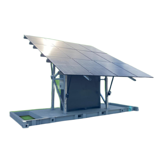
Page 4: Powerhub Dimensions & Parts
Weight: 330kg + 40kg per battery Internal Components Inverter Charger MPPT Solar Charge Controller GX Touch System Monitoring PV Solar DC Isolator MPPT Battery DC Isolator Battery System DC Isolator AC Switchboard 48V Batteries Commodore Australia Page 4 of 30 Issue Date 10/01/2024... -
Page 5: Powerhub Parts Explanation
Pylontech may suggest the batteries should be installed horizontally, Pylontech’s engineers have also confirmed via email to Commodore that this mounting position is suitable. If you’d like to see a copy of this please don’t hesitate to ask. -
Page 6: Ac Switchboard Explained
Power Hub output to the equivalent site. and you need to connects to the switchboard. Inverter installed. rely on changeover generator, switch switch to the left. to generator only AC Switchboard Commodore Australia Page 6 of 30 Issue Date 10/01/2024... -
Page 7: Dc Switchboard Explained
This is a prewired 48v to 12v converter which is used to power the router on the board when a PV Array DC MPPT Battery fronius is sold with the system. Isolator DC Isolator Commodore Australia Page 7 of 30 Issue Date 10/01/2024... -
Page 8: Communication Cables Explained
Cerbo and the BMS screen) From the Fronius Direct devices are Can tag is New MK2 version WSD port to inverter connected to the has all 3 x USB K1 contact. batteries Commodore Australia Page 8 of 30 Issue Date 10/01/2024... -
Page 9: Ac Switchboard Wiring
A Main Switch Standalone Supply, PV Inverter Main Switch (if present) Change over switch, Generator Supply Switch, RCBO for the 15A outlet and a Sub Board Breaker are all pre installed. Commodore Australia Page 9 of 30 Issue Date 10/01/2024... -
Page 10: Single Line Diagram
Note: The use of plug connecting generating sets is not permitted due to the possibility that the pins on the connection cord may come live due to “back feeding” from the inverter. Commodore Australia Page 10 of 30 Issue Date 10/01/2024... -
Page 11: Power Hub Ac & Dc Entries
DC cable across the Power Skid base, separating AC & DC cables, and connect DC into the right side of the Power Hub. Pre wired plugs are sitting in the solar skid ready for connection, Commodore Australia Page 11 of 30 Issue Date 10/01/2024... -
Page 12: Earth Stake Connection
A licensed electrician needs to make the main Earth Electrode Connection, there is an earth cable tail pre connected and stored in the cable tray ready for connection to the earth electrode. Commodore Australia Page 12 of 30 Issue Date 10/01/2024... -
Page 13: Startup Procedure
O F F - G R I D S Y S T E M / / I N S T A L L A T I O N Step 2: Startup Procedure (inside Powerhub) 1. Turn on all Battery Switches if present (in battery cabinet) 2. -
Page 14: Shutdown Procedure
8.Turn off all Battery Circuit Breakers located on front of batteries if present 9.Turn On/Off Switch to OFF on Lithium batteries 10.Startup Procedure is the reverse of the Shutdown Procedure Quattro Multiplus On/Off Button Commodore Australia Page 14 of 30 Issue Date 10/01/2024... -
Page 15: Set Up Skid Panels + Bracing
Take note of the colour code used for each section Attachment point Commodore Australia Page 15 of 30 Issue Date 10/01/2024... - Page 16 Solar Skid, and then Raise Solar Frames using control buttons in cabinet 5. Secure ends of bracing to main upright pole via 8mm bolt provided Support Bracing highlighted in Green Commodore Australia Page 16 of 30 Issue Date 10/01/2024...
-
Page 17: Getting System Online
If the system comes with a TP-Link router which is typically when there is a Fronius Solar inverter, instead of the ethernet cable plugging into the Cerbo it will plug into the TP-Link WAN port. Commodore Australia Page 17 of 30 Issue Date 10/01/2024... - Page 18 *you can now return to the settings to enter your password, then press list using the Back arrow at the top the tick at the bottom right of the left of the screen* screen* Commodore Australia Page 18 of 30 Issue Date 10/01/2024...
- Page 19 ** If the internet disconnects from the Cerbo follow these steps to reboot the Cerbo, this won’t turn off your power. From the Home Screen click Settings > General > Reboot. When click Reboot this will reconnect the internet. Commodore Australia Page 19 of 30 Issue Date 10/01/2024...
- Page 20 Select 'Add Installation' which takes you to the screen shown below. Note: Systems from Commodore will already be registered on the VRM portal using the customers email address. Go to ‘Add Installation’ will send us an email asking us to grant you access.
- Page 21 3. Your VRM Portal ID is shown: Enter your Portal ID in the 'Add Installation' page of the VRM portal as shown above and click 'Request access'. A Commodore Support member will then receive an email asking to approve access.
-
Page 22: Generator Connection & Settings
O F F - G R I D S Y S T E M / / I N S T A L L A T I O N Step 4: Generator Installation Commodore Generator Installation When installing a Commodore Generator into your Off Grid Solar System, please watch your relevant video (Air-Cooled or Water-Cooled) by scanning the QR Codes below. Air-Cooled Commodore Diesel... - Page 23 Device list. Perform a test run of the generator - preferably while the batteries are below 85%. If the generator power seems unstable, try reducing the current limit. Commodore Australia Page 23 of 30 Issue Date 10/01/2024...
- Page 24 List and then select "Relay": again to change: Step 3: Select Generator start/stop from the Step 4: Once done, press the back arrow list: at the top left to return to the Settings list: Commodore Australia Page 24 of 30 Issue Date 10/01/2024...
- Page 25 Step 3: Go down to Settings: the generator fails to start: Step 6: Select Battery SOC (State of Step 5: Select "Conditions": Charge) Commodore Australia Page 25 of 30 Issue Date 10/01/2024...
- Page 26 Setting a Start value of 47v and a Stop value of 55v would be appropriate for most lead-acid battery banks. The 'Start after the condition is reached for' setting allows a delay prior to starting the generator, set this to '120s'. Commodore Australia Page 26 of 30 Issue Date 10/01/2024...
- Page 27 Enable "Quiet hours" in the Generator Example Battery State of Charge start start/stop 'Settings' menu: and stop conditions for Quiet hours: Commodore Australia Page 27 of 30 Issue Date 10/01/2024...
- Page 28 Remember - if you don't set a run duration in 'Run for' the generator will keep running until it is switched off here - or until it runs out of fuel! Commodore Australia Page 28 of 30 Issue Date 10/01/2024...
-
Page 29: Power Skid Fold Out
Step 5: Power Skid Fold Out Power Skid Fold Out Your Power Skid travels, and will arrive in the folded position just like the images attached. In order to expand the solar array, Commodore Australia Page 29 of 30 Issue Date 10/01/2024... -
Page 30: Final Checks & Torque Settings
Cerbo GX Touch, you are finished the installation! Contact Us With Any Questions If you have any questions, please call our support team on 1300 669 256 or email support@commodoreaustralia.com.au Commodore Australia Page 30 of 30 Issue Date 10/01/2024...
Need help?
Do you have a question about the POWERHUB and is the answer not in the manual?
Questions and answers