
Summary of Contents for Metergy Quadlogic miniQloset QBRICK-MQ-2P24M
- Page 1 User manual Ver-1.3 Revision Date: 03/2024 miniQloset Multi-Channel Electric Meter User Manual Quadlogic Controls Corp www.quadlogic.com Tel: +1(212) 930 9300...
- Page 2 User manual Ver-1.3 Revision Date: 03/2024 Read Me Read this user manual carefully before installing, operating, or maintaining the miniQloset multi- channel electric meter. Safety must be the priority when reviewing all installation guidelines described in this document. Installation, operation, and maintenance of the miniQloset multi- channel electric meter must be performed by qualified and trained professionals with experience in high voltage and current devices and metering equipment.
-
Page 3: Table Of Contents
User manual Ver-1.3 Revision Date: 03/2024 Table of Contents Page 1. PACKAGE CONTENTS 2. OVERVIEW 2.1 Features 3. SPECIFICATIONS 4. INSTALLATION 4.1 Mounting 4.2 Connection Terminal Access 4.3 Hardware Tamper Protection 4.4 Meter Layout 4.5 Communication Wiring Installation 4.6 Reference Voltage (V-REF) Input Installation 4.7 CT Inputs Installation 4.8 Installing Auxiliary Power Supply 4.9 Final Steps... -
Page 4: Package Contents
User manual Ver-1.3 Revision Date: 03/2024 1. PACKAGE CONTENTS ● 1 miniQloset meter (QBRICK-MQ-2P24M or QBRICK-MQ-3P16M) ● 1 miniQloset Service Kit (1 per installation site, P/N 76-MQ-SERVICEKIT) ○ 2 CT Shorting PCBs ○ 20 Lead Sealing Screws ○ 20 Current Transformer Replacement Plugs ○... -
Page 5: Features
User manual Ver-1.3 Revision Date: 03/2024 2.1 Features Table 1: Measurement Functions Function Parameter Metering Unit Channel Point Voltage ● Current ● Active Power ● ● Real-Time Reactive Power ● ● kVAr Parameters Apparent Power ● ● Power Factor ● ●... - Page 6 User manual Ver-1.3 Revision Date: 03/2024 Event Log The miniQloset meter records up to 1000 event logs. These logs are stored as Sequence of Events (SOE) records for meter diagnostics and troubleshooting. See Appendix G for additional information about SOE records.
-
Page 7: Specifications
User manual Ver-1.3 Revision Date: 03/2024 3. SPECIFICATIONS Reference Standards Meter Accuracy: ANSI-C12.20:2015 Safety: UL61010-1-2012 UL61010-2-030:2012 CSA C22.2 NO 61010-1 CSA C22.2 NO 61010-2-030 Reference Voltage and Ref Voltage Range: ANSI tested for 120 VAC (L-N) Current Input Ratings (+/- 10% tolerance) Current Inputs: 0-100 mA Frequency:... - Page 8 User manual Ver-1.3 Revision Date: 03/2024 Figure 1: MiniQloset Dimensions Table 2: Accuracy Specifications* Parameter Accuracy (+/-) Resolution (Primary side) Voltage 0.2% 0.01 V Current 0.2% 0.01 A Active Power 0.5% 0.01 W Reactive Power 0.5% 0.01 VAR Apparent Power 0.5% 0.01 VA Power Factor...
-
Page 9: Installation
User manual Ver-1.3 Revision Date: 03/2024 4. INSTALLATION INSTRUCTIONS This chapter details the installation procedures for the miniQloset. There are general and configuration- specific instructions for the miniQloset. Configuration-specific instructions are stated as such. Critical: Use wiring instructions that correspond to the configuration of the meter under installation. Follow instructions and warnings to ensure proper operation of equipment and to reduce the risk of electric shock or other hazardous conditions. -
Page 10: Mounting
User manual Ver-1.3 Revision Date: 03/2024 4.1 Mounting The miniQloset meter has two mounting options (Figure 2). The meter can be directly fastened onto a wall or panel by using the integrated fold-out feet, or the meter can be mounted on a 35 mm DIN rail with the meter’s integrated DIN rail clip. -
Page 11: Connection Terminal Access
User manual Ver-1.3 Revision Date: 03/2024 4.2 Connection Terminal Access The miniQloset wiring terminals are protected by four plastic flaps. Each side of the meter has an upper and lower flap, as shown in Figure 3 below. MiniQloset terminal access instructions: 1. -
Page 12: Meter Layout
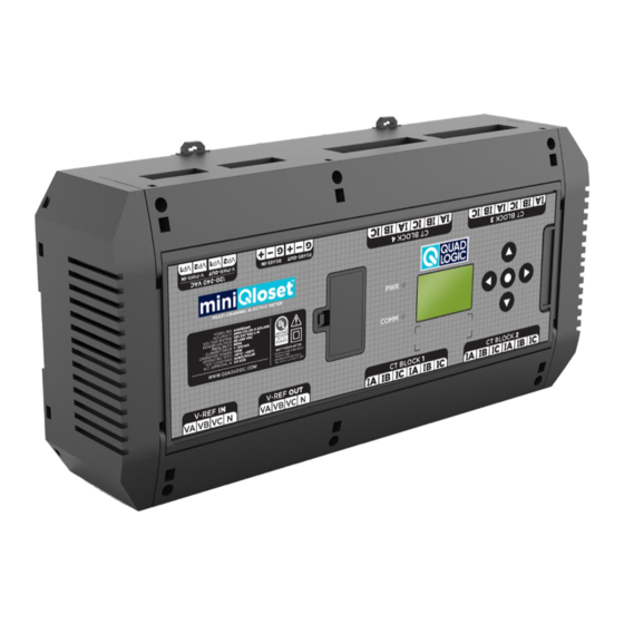
User manual Ver-1.3 Revision Date: 03/2024 4.4 Meter Layout Figure 4: Front Face Layout Figure 5: V-REF Side Terminals Figure 6: V-PWR Side Terminals Quadlogic Controls Corp. www.quadlogic.com Tel: +1(212) 930-9300... -
Page 13: Communication Wiring Installation
User manual Ver-1.3 Revision Date: 03/2024 4.5 Communication Wiring Installation For remote data access the miniQloset can be connected to a QTao meter data hub or third-party building management system via the RS-485 header. See QFamily RS-485 Wiring Guidelines (available at www.quadlogic.com) for detailed wiring specs and instructions. -
Page 14: Ct Inputs Installation
User manual Ver-1.3 Revision Date: 03/2024 4.7 CT Inputs Installation Current input requirements: ● The standard input current for the miniQloset is 100 mA. ● Use class 0.1 CTs to maintain ANSI class 0.5-meter accuracy. ● For NY residential installations the NYPSC requires CT models CT162W or CT163W (available from Quadlogic Controls Corp.) ●... -
Page 15: Installing Auxiliary Power Supply
User manual Ver-1.3 Revision Date: 03/2024 Table 4: CT Wiring Extension Specifications CT secondary Total CT secondary wire size (AWG) wire length (ft) # 20 # 18 # 16 Note: CT wiring diagram is different for 2EL and 3EL configurations. See Appendix A for detailed diagrams. CT Inputs Installation Steps: 1. -
Page 16: Connecting Multiple Miniqloset Units Together
User manual Ver-1.3 Revision Date: 03/2024 4.10 Wiring Multiple miniQloset Units The miniQloset has in/out terminals for V-REF, V-PWR, and RS-485 communication. Use the following diagrams to daisy chain multiple miniQloset together. WARNING: Verify power is OFF when connecting wires. Note: ●... -
Page 17: Display & Operation
User manual Ver-1.3 Revision Date: 03/2024 5. DISPLAY & BUTTON OPERATION The miniQloset has a 32 x 23 mm LCD screen for viewing metering parameters and meter configuration. Some configuration options may be changed from the display. After powering up, the miniQloset will show a welcome screen and perform a self-check. Four directional arrow keys and a central selection button are located to the right of the LCD screen. -
Page 18: Appendix A - Wiring Diagrams
Appendix A - Wiring Diagrams Figure 1: Voltage and Communication Wiring Diagrams Quadlogic Controls Corp. www.quadlogic.com Tel: +1(212) 930-9300... - Page 19 Figure 2: MiniQloset 2EL – CT Connections to Metering Points 1 - 6 Quadlogic Controls Corp. www.quadlogic.com Tel: +1(212) 930-9300...
- Page 20 Figure 3: MiniQloset 3EL CT Connections to Metering Points Quadlogic Controls Corp. www.quadlogic.com Tel: +1(212) 930-9300...
-
Page 21: Appendix B - Menu Tree Navigation
User manual Ver-1.3 Revision Date: 12/2023 Appendix B - Menu Tree Navigation Table 1: Display Navigation Button Functions 1. Scroll up through menu rows (see display tree). 2. Scroll up through metering pts when a meter pt. parameter is displayed 3. - Page 22 User manual Ver-1.3 Revision Date: 12/2023 Figure 1: Main Menu - 3EL Model Quadlogic Controls Corp. www.quadlogic.com Tel: +1(212) 930-9300...
- Page 23 User manual Ver-1.3 Revision Date: 12/2023 Figure 2: Main Menu - 2EL Model Quadlogic Controls Corp. www.quadlogic.com Tel: +1(212) 930-9300...
- Page 24 User manual Ver-1.3 Revision Date: 12/2023 Figure 3: Configuration Menu ● For screens that allow changes (down arrow in upper right corner) push the down button to enter edit mode. ● Some configuration parameters may be locked by default. Contact Quadlogic if you have any issues. Using the Configuration Menu - examples: Reset Modbus packet statistics record (Main menu under Modbus Debugging) Change Display Units to secondary mA:...
-
Page 25: Appendix C - Modbus Register Map
User manual Ver-1.3 Revision Date: 12/2023 Appendix C - MODBUS Register Map Usage MODBUS © Protocol Table 1: MODBUS RTU Frame Format Address code 1 BYTE MODBUS device address 1-247 Function code 1 BYTE Indicates the function code Starting address, high byte Starting address, low byte Data code 4 BYTES... -
Page 26: Appendix D - Modbus Functions
User manual Ver-1.3 Revision Date: 12/2023 Appendix D – MODBUS Meter Data Registers Table 3: Basic Parameters (per channel/CT), Read Only, “03H” Code to Read Reg Addr. Parameter Data # of regs Description float float float Phase to line voltage, unit V …... - Page 27 User manual Ver-1.3 Revision Date: 12/2023 Reg Addr. Parameter Data # of regs Description unit 0.001 kVARh Eq2_2 Long Eq3_2 Long … … … … Eq48_2 Long Eq1_3 Long Eq2_3 Long Quadrant 3 reactive energy, Eq3_3 Long unit 0.001 kVARh …...
- Page 28 User manual Ver-1.3 Revision Date: 12/2023 Table 4: Real-time Parameters per Metering Point (primary side value) Reg Addr. Parameter Data # of regs Description 1344 P∑1 float 1346 P∑2 float 1348 P∑3 float Active power, unit kW … … … …...
- Page 29 User manual Ver-1.3 Revision Date: 12/2023 Reg Addr. Parameter Data # of regs Description 1780 Eqz3_3 Long Quadrant 3 reactive energy … … … … unit 0.001 kVARh 1822 Eqz24_3 Long 1824 Eqz1_4 Long 1826 Eqz2_4 Long Quadrant 4 reactive energy, 1828 Eqz3_4 Long...
- Page 30 User manual Ver-1.3 Revision Date: 12/2023 Table 5: Each CT Channel Real-time Fundamental Parameters (primary side value) Reg Addr. Parameter Data # of regs Description 28000 float 28002 float 28004 float Phase to line voltage, unit V … … … …...
- Page 31 User manual Ver-1.3 Revision Date: 12/2023 Table 6: Metering Point Real-Time Fundamental Parameters (primary side values) Reg Addr. Parameter Data # of regs Description 28576 P∑1 float 28578 P∑2 float 28580 P∑3 float Active power, unit kW … … … …...
-
Page 32: Appendix E - Meter Configuration, Read And Write
User manual Ver-1.3 Revision Date: 12/2023 Appendix E – Modbus Map: Meter configuration, read and write (read “03H”, write “06H/10H” Table 1: Read and Write Registers (NOT write-protected by K-485 switch) # of Item Data Description Addr. regs 4020 RS485 address 1-247 0: 2400 4: 38400... - Page 33 User manual Ver-1.3 Revision Date: 12/2023 Table 2: Read and Write Registers (write-protected by the K-485 switch). # of Item Data Description Addr. regs Default 1000 4027 Pulse constant Range: 100-65535 (per Wh, VARh, VAh) 0: Total wave energy value 1: Fundamental wave energy value Note: global setting;...
-
Page 34: Appendix F - Interval Record Retrieval, "03H"To Read; "06H" Or "10H"To Write
User manual Ver-1.3 Revision Date: 12/2023 Appendix F – Modbus Map Interval record retrieval, “03H”to read; “06H” or “10H”to write The meter records the most recent 180 days of energy interval data in flash memory. The ReadyGo command is used to get data from the Flash memory into the modbus registers, then MODBUS commands are used to read this data. - Page 35 User manual Ver-1.3 Revision Date: 12/2023 Using ReadyGo command to retrieve interval records by page number: The saved interval record data in flash can be accessed by page number or by date. The user can determine the desired page number by checking the flash page index to locate interval record data for a certain date.
- Page 36 User manual Ver-1.3 Revision Date: 12/2023 Table 5: MiniQloset ReadyGo Response Example: Example Definition Value description value Address Meter RS485 address Write operation Write command code 15 86H Register start Write from 5510 00 02H Write register length 2 registers High bit of CRC Low bit of CRC Caution: If an RTC change causes Flash memory to have multiple records for the same date,...
- Page 37 User manual Ver-1.3 Revision Date: 12/2023 Table 7: ReadyGo Requested Interval Record Registers # of Reg Addr. Item Data Description regs Epz1+ to Epz24+ Metering point_1 to Metering point_24, 6000-6047 long Interval record_1 Active energy delivered, unit 0.001 kWh Epz1- to Epz24- Metering point_1 to Metering point_24, 6048-6095 long...
-
Page 38: Appendix G- Soe Record, Read Only, "03" Code To Read
User manual Ver-1.3 Revision Date: 12/2023 Appendix G- Sequence of Events Record, read only, “03” code to read Table 1: SOE Records and Event Codes # of Reg Addr. Item Data Description regs 30000 Event code, (see below) Serious failures counter, (see below) 30001 Bit 15-8: Serious failure count range:0-255 Bit 7-0: Daily counter... - Page 39 User manual Ver-1.3 Revision Date: 12/2023 Sequence of Events (SOE) Status: Reading and Resetting Status Flags The meter provides a 32-bit flag register to indicate the occurrence of certain events. Each flag is one bit, there are a total of 32 flag bits accessed through 2 modbus registers. A given flag bit is set by the meter firmware when the listed event occurs.
-
Page 40: Appendix H- Additional Registers
User manual Ver-1.3 Revision Date: 12/2023 Appendix H: Additional Registers Copy of accumulated energy data from the 6 most recent recording intervals. Read only, “03H” code to read. The meter automatically maintains a copy of the accumulated energy data for the 6 most recent recording intervals in the following modbus registers. - Page 41 User manual Ver-1.3 Revision Date: 12/2023 Aliases of Device Info, read only, “03H” code to read. Table 4: Aliases of Device Info # of Item Data Description Addr. regs 65500 Serial number low 16bit 65501 Serial number high 16bit 65502 Software version 0: 3P4W-3EL Wye (16 3ph metering points) 65503...
Need help?
Do you have a question about the Quadlogic miniQloset QBRICK-MQ-2P24M and is the answer not in the manual?
Questions and answers