Table of Contents
Advertisement
Quick Links
Advertisement
Table of Contents

Related Manuals for Nidec SI-I/O 24 Plus

Summary of Contents for Nidec SI-I/O 24 Plus
- Page 1 User Guide SI-I/O 24 Plus Part Number: 0478-0704-04 Issue: 4...
-
Page 2: Table Of Contents
Getting Started ........13 Encoder setup .............13 Selecting the module for motor control feedback .............13 Parameters ...........14 Menu 1x - Encoder interface, freeze system and thermistor input ...........14 Menu 2x - Digital I/O ...........24 Diagnostics ..........26 Trips ..............26 SI-I/O 24 Plus User Guide... - Page 3 The Nidec logo is a trade mark of Nidec Corporation. The Control Techniques logo is a trade mark owned by Nidec Control Techniques Limited. All other marks are property of their respective owners.
-
Page 4: Safety Information
The drive contains capacitors that remain charged to a potentially lethal voltage after the AC supply has been disconnected. If the drive has been energized, the AC supply must be isolated at least ten minutes before work may continue. SI-I/O 24 Plus User Guide... -
Page 5: Mechanical Hazards
It is the responsibility of the installer to ensure that the equipment or system into which the product is incorporated complies with the relevant EMC legislation in the place of use. SI-I/O 24 Plus User Guide... -
Page 6: Introduction
8 optically isolated digital outputs. The SI-I/O 24 Plus module has been designed to work alongside the PTi210 Motion Made Easy option module to provide the same digital I/O and main motor encoder input as the Epsilon EP servo drives. A 44-way high density D-type connector is used to provide both the encoder input and digital I/O connections. -
Page 7: Installing The Option Module
The SI option mounting kit can be ordered from the supplier of the drive. Refer to the Digitax HD M75X Series Installation and Technical Guide for further information. NOTE Once fitted, the option module remains at an angle with respect to the drive. SI-I/O 24 Plus User Guide... -
Page 8: Electrical Installation
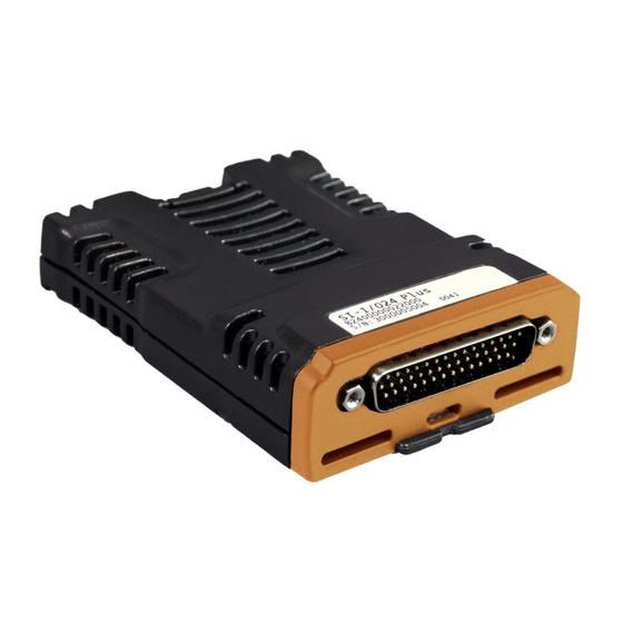
Parameters Diagnostics Module Electrical installation Terminal descriptions The module uses a single 44-pin male high density D-type connector for the encoder input and the digital I/O connections. Figure 4-1 SI-I/O 24 Plus connector Encoder +Vdc I/O 0V +Vdc In Encoder... -
Page 9: Electrical Specifications
< 5 V or an input current of < 0.5 mA Absolute maximum voltage range -3 V to +30 V Compliance IEC61131-2 Type 1 24 Vdc digital input Update rate 250 µs 0 V reference connection I/O 0V Common on pins 15, 30 and 44 SI-I/O 24 Plus User Guide... -
Page 10: External 24 V Power Supply Requirements
Termina on resistors Pin 3 Ω Pin 2 Pin 18 Ω Pin 17 Encoder cable Pin 32 Ω Pin 31 Encoder Pin 5 Ω Pin 4 Pin 20 Ω Pin 19 Pin 34 Ω Pin 33 SI-I/O 24 Plus User Guide... -
Page 11: Encoder Wiring And Shield Connections
To ensure suppression of radio frequency emission, observe the following: • Use a cable with an overall shield • Clamp the overall shield to grounded metallic surfaces at both the encoder and the drive, as illustrated in Figure 4-4. SI-I/O 24 Plus User Guide... -
Page 12: Optional Breakout Board
The ground connections on terminals 45 and 46 of the breakout board are connected to the shell of the 44-way high density D-type connector. When the breakout board is connected to the SI-I/O 24 Plus module, terminals 45 and 46 will be connected to the encoder 0 V on terminal 16 of the breakout board, and to 0 V on the drive. -
Page 13: Getting Started
Option Slot Setting for Motor Control Feedback Select (03.026) on the drive P1 Slot 1 (2) P1 Slot 2 (4) P1 Slot 3 (6) SI-I/O 24 Plus User Guide... -
Page 14: Parameters
Position Feedback Lock (1x.050) Normalised Normalised Position Marker Position 1x.058 1x.059 Normalisation Turns (1x.057) Speed Feedback d/dt Feedback Filter(1x.042) 1x.027 Reference Destination (1x.046) Reference Maximum Reference(1x.043) 1x.045 Reference Scaling (1x.044) SI-I/O 24 Plus Encoder Input SI-I/O 24 Plus User Guide... - Page 15 {Slotx Error.Motor Th} trip detect 1x.119 Thermistor Trip Threshold (1x.120) {Slotx Error.Motor Th} Thermistor Reset Threshold (1x.121) {Slotx Error.Motor Th SC} {Slotx Error.Motor Th SC} trip detect SI-I/O 24 Plus Freeze System and Thermistor Input SI-I/O 24 Plus User Guide...
- Page 16 Thermistor Fault Detection None (0), Temperature (1), Temp or Short (2) None (0) Read / Write Read-only Bit parameter Text string Number parameter Binary parameter Destination No default value Not cloneable Protected Filtered User save SI-I/O 24 Plus User Guide...
- Page 17 Power-up write Type 16 Bit Volatile Display format Standard Coding RO, ND, NC, PT, BU This parameter displays the ID number for the option module. For the SI-I/O 24 Plus module this is 108. 1x.002 Firmware Version Minimum Maximum 99999999 Default...
- Page 18 32 Bit User Save Display format Standard Coding This parameter defines the number of lines per revolution for the AB quadrature encoder connected to the module encoder interface. The maximum permissible input frequency is 500 kHz SI-I/O 24 Plus User Guide...
- Page 19 4 ms. Although Reference Destination (1x.046) can be changed at any time, the destination target is only updated on drive reset. 1x.044 Reference Scaling Minimum 0.000 Maximum 4.000 Default 1.000 Decimal places 3 Units Update rate Background read Type 16 But User Save Display format Standard Coding See Maximum Reference (1x.043). SI-I/O 24 Plus User Guide...
- Page 20 Normalised Position (1x.058) and Normalised Marker Position (1x.059). 1x.058 Normalisation Position Minimum -2147483648 Maximum 217483647 Default Decimal places 0 Units Update rate 250 µs write Type 32 Bit Volatile Display format Standard Coding RO, ND, NC, PT See Normalisation Turns (1x.057). SI-I/O 24 Plus User Guide...
- Page 21 Freeze events are produced on the rising edge of the common freeze signal. If Freeze Flag (1x.104) is 0 then the first rising edge causes the freeze position to be stored and Freeze Flag (1x.104) to be set to 1. If further rising edges occur the freeze position is updated. SI-I/O 24 Plus User Guide...
- Page 22 Type 1 Bit Volatile Display format Standard Coding RW, ND, DC, PT The freeze flag is set when a marker freeze event occurs. If 0 is written to this parameter the freeze flag is cleared. SI-I/O 24 Plus User Guide...
- Page 23 If short circuit detection is enabled then a Motor Th SC trip is initiated if Thermistor Feedback (1x.119) is below 50 ohms. Key to parameter coding Read write Read-only Text string No default value Not cloneable Protected Unipolar or bit parameter with default of 1 Voltage rating dependent Filtered Variable maximum Destination parameter Pseudo read-only SI-I/O 24 Plus User Guide...
-
Page 24: Menu 2X - Digital I/O
2x.021 .022 .023 .024 .025 .026 .027 .028 Output Register (2x.011) SI-I/O 24 Plus Digital Inputs and Outputs 6.2.2 Menu 2x single line descriptions Parameter Range ( ) Default ( ) Type 2x.010 Input Register 0000000000000000 to 1111111111111111 ND NC 2x.011... - Page 25 Key to parameter coding Read write Read-only Text string No default value Not cloneable Protected Unipolar or bit parameter with default of 1 Voltage rating dependent Filtered Variable maximum Destination parameter Pseudo read-only SI-I/O 24 Plus User Guide...
-
Page 26: Diagnostics
Ensure that the EMC recommendations in the Watchdog Error to a watchdog timeout or hard fault error. installation guide for the drive have been followed. • If this trip persists please consult the supplier of the module. SI-I/O 24 Plus User Guide... - Page 28 0478-0704-04...
Need help?
Do you have a question about the SI-I/O 24 Plus and is the answer not in the manual?
Questions and answers