Table of Contents
Advertisement
Quick Links
User's Manual
For
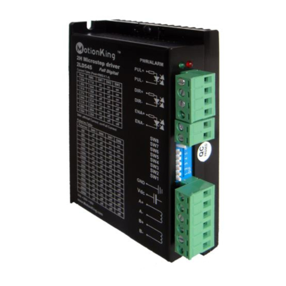
2LD545
Fully Digital Stepping Driver
Version 1.0
©2014 All Rights Reserved
Attention: Please read this manual carefully before using the driver!
MotionKing(China) Motor Industry Co., Ltd.
T: (86)519-8988 6261
F: (86)519-8515 1172
Web site:
www.MotionKing.com
E-Mail:
sales@MotionKing.com
Advertisement
Table of Contents

Summary of Contents for MotionKing 2LD545
- Page 1 User’s Manual 2LD545 Fully Digital Stepping Driver Version 1.0 ©2014 All Rights Reserved Attention: Please read this manual carefully before using the driver! MotionKing(China) Motor Industry Co., Ltd. T: (86)519-8988 6261 F: (86)519-8515 1172 Web site: www.MotionKing.com E-Mail: sales@MotionKing.com...
- Page 2 MotionKing’s general policy does not recommend the use of its products in life support or aircraft applications wherein a failure or malfunction of the product may directly threaten life or injury.
-
Page 3: Table Of Contents
Contents Table of Contents 1. Introduction, Features and Applications ..............1 Introduction ......................1 Features ......................... 1 Applications......................1 2. Specifications ......................2 Electrical Specifications ..................2 Mechanical Specifications ..................2 Elimination of Heat ....................2 Operating Environment and other Specifications ..........3 3. - Page 4 Contents Dynamic current setting ................10 Standstill current setting ................10 8. Wiring Notes......................10 9. Typical Connection ....................11 10. Sequence Chart of Control Signals ................ 11 11. Protection Functions ....................12 Over-current Protection ................12 Over-voltage Protection ................12 Phase Error Protection .................
-
Page 5: Introduction, Features And Applications
Suitable for a wide range of stepping motors, from NEMA size 17 to 34. It can be used in various kinds of machines, such as laser cutters, laser markers, high precision X-Y tables, labeling machines, and so on. Its unique features make the 2LD545 an ideal solution for applications that require both low-speed smoothness and high speed performances. -
Page 6: Specifications
Contents 2. Specifications Electrical Specifications (T = 25℃/77℉) 2LD545 Parameters Typical Unit Output current 4.5 (3.2 RMS) Supply voltage +30~+40 Logic signal current Pulse input frequency MΩ Isolation resistance Mechanical Specifications (unit:mm, 1 inch = 25.4 mm) Figure 1: Mechanical specifications Elimination of Heat ... -
Page 7: Operating Environment And Other Specifications
Approx. 280g (10 oz) 3. Pin Assignment and Description The 2LD545 has two connectors, connector P1 for control signals connections, and connector P2 for power and motor connections. The following tables are brief descriptions of the two connectors. More detailed descriptions of the pins and related issues are presented in section 4, 5, 9. -
Page 8: Selecting Active Pulse Edge And Control Signal Mode
The 2LD545 can accept differential and single-ended inputs (including open-collector and PNP output). The 2LD545 has 3 optically isolated logic inputs which are located on connector P1 to accept line driver control signals. These inputs are isolated to minimize or eliminate electrical noises coupled onto the drive control signals. -
Page 9: Connecting The Motor
Figure 3: Connection to PNP signal (common-cathode) 5. Connecting the Motor The 2LD545 can drive any 2-pahse and 4-pahse hybrid stepping motors. Connections to 4-lead Motors 4 lead motors are the least flexible but easiest to wire. Speed and torque will depend on winding inductance. -
Page 10: Half Coil Configurations
Contents Half Coil Configurations As previously stated, the half coil configuration uses 50% of the motor phase windings. This gives lower inductance, hence, lower torque output. Like the parallel connection of 8 lead motor, the torque output will be more stable at higher speeds. This configuration is also referred to as half chopper. In setting the driver output current multiply the specified per phase (or unipolar) current rating by 1.4 to determine the peak output current. -
Page 11: Parallel Connections
6. Power Supply Selection The 2LD545 can match medium and small size stepping motors (from NEMA frame size 14 to 34) made by MotionKing or other motor manufactures around the world. To achieve good driving performances, it is important to select supply voltage and output current properly. -
Page 12: Multiple Drivers
Instead, please connect them to power supply separately. Selecting Supply Voltage The power MOSFETS inside the 2LD545 can actually operate within +20 ~ +50VDC, including power input fluctuation and back EMF voltage generated by motor coils during motor shaft deceleration. -
Page 13: Microstep Resolution Selection
Contents Microstep Resolution Selection When it’s not in software configured mode, microstep resolution is set by SW5, 6, 7, 8 of the DIP switch as shown in the following table: Pulse/rev Pulse/rev Micro Micro step step 1000 2000 1600 4000 3200 5000 6400... -
Page 14: Dynamic Current Setting
The current automatically reduced to 60% of the selected dynamic current one second after the last pulse. Theoretically, this will reduce motor heating to 36% (due to P=I *R) of the original value. If the application needs a different standstill current, please contact MotionKing. 8. Wiring Notes ... -
Page 15: Typical Connection
Contents 9. Typical Connection A complete stepping system should include stepping motor, stepping driver, power supply and controller (pulse generator). A typical connection is shown as figure 9. DM556 Driver 2LD545 Driver Controller 270Ω PUL+ PUL- 270Ω DIR+ DIR- 270Ω... -
Page 16: Protection Functions
Low level width not less than 2.5s. 11. Protection Functions To improve reliability, the driver incorporates some built-in protection functions. The 2LD545 uses one RED LED to indicate what protection has been activated. The periodic time of RED is 3 s (seconds), and how many times the RED turns on indicates what protection has been activated. -
Page 17: Frequently Asked Questions
Contents Over-voltage protection Phase error protection 12. Frequently Asked Questions In the event that your driver doesn’t operate properly, the first step is to identify whether the problem is electrical or mechanical in nature. The next step is to isolate the system component that is causing the problem. - Page 18 Contents Current setting is too small Motor is undersized for the application Motor stalls during acceleration Acceleration is set too high Power supply voltage too low Inadequate heat sinking / cooling Excessive motor and driver heating Automatic current reduction function not being utilized Current is set too high...
Need help?
Do you have a question about the 2LD545 and is the answer not in the manual?
Questions and answers