Advertisement
Quick Links
USER INSTRUCTIONS
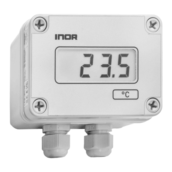
LCD-W110
Loop Powered indicator
with backlight for field mounting
The user instruction must be read prior to adjustment and/or installation.
All information subject to change without notice.
MEASUR E O F SUCCE SS
INOR Process AB, PO Box 9125, SE-200 39 Malmö, Sweden,
Phone: +46 40 312 560, Fax: +46 40 312 570, E-mail: support@inor.se
INOR Transmitter OY, Unikkotie 13, FI-01300 Vantaa, Finland,
Phone:+358 10 421 7900, Fax: +358 10 421 7901, E-mail: myynti@inor.fi
INOR Transmitter GmbH, Am See 24, D-47279 Duisburg, Germany,
Phone: +49-203 7382 762 0, Fax: +49-203 7382 762 2, E-mail: info@inor-gmbh.de
KROHNE Temperature Division INOR, 55 Cherry Hill Drive,
Beverly, MA 01915, United States
Phone: +1 978 826 6900, Fax: +1 978 535 1720, E-mail: inor-info@krohne.com
www.inor.com, www.krohne-inor.se
www.krohne-inor.fi, www.inor-gmbh.de
This product should not be mixed with other kind of scrap, after usage.
It should be handled as an electronic/electric device.
MEAS UR E O F SUC CE SS
INTRODUCTION
LCD-W110 is a loop powered digital indicator to be connected directly in a
4-20 mA loop without need for external power supply.
The indicator show numeric values in the range from -1999 to 9999 propor-
tional to the 4-20 mA input signal on a digital display.
LCD-W110 is designed for field mounting on wall, pipe or DIN rail and has
a rugged and splashproof housing for mounting directly into an industrial
environment.
GENERAL INFORMATION
Configuration of the indicator is done either with NFC and the smartphone
app INOR Connect or with three push buttons.
The indicator can be connected to the 4-20 mA loop of any normal 2-wire
transmitter.
The field indicator LCD-W110 can be equipped with an integrated Inor In-
Head transmitter of any type for direct sensor input.
LCD-W110 is equipped with a rugged and splashproof IP 65 / NEMA 4X
housing with double cable conduits for convenient installation, one blanking
plug is included.
The indicator is designed for ambient temperatures between -20 to +70 °C
(-4 to +158 °F).
This manual describes in short form the various functions and technical data
of the display, for a more detailed description please refer to the specific
manual for the display module LCD-D100.
Installation, assembly, start-up and maintenance may only be
performed by appropriately trained personnel.
DATA (short form)
Input Current
4-20 mA
Maximum current
30 mA
Minimum current for operation
~3.5 mA
Voltage drop
4.2 V
Indication
Display
7-segment black LCD with clear background
Backlight
White LED powered from the 4-20 mA loop
Indication range
4 digits (-1999 to 9999)
Digit height
17.8 mm / 0.7"
Decimals
Selectable, 0 to 3
Under range / Over range
Flashing symbols Lo (I ≤ 3.6 mA) /
HI (I ≥ 21.0 mA)
Engineering units
Set of self-adhesive labels included for
units: °C, °F, mA, mV, V, bar, mbar, Pa, kPa,
MPa, pH, %, s, ms, μs, mm, cm, m
Response time
Appr. 1 s
Power on delay: 5 s and stable after 1 min
Temperature influence
≤ ±0.01 % FS / °C
Configuration method
3 push buttons or NFC, located on the rear
of the display
Operation temperature
-20 to +70 °C / -4 to +158 °F
Typical accuracy
±0.05% of span ±1 digit
Dimensions
80 x 110 x 65 mm / 3.15 x 4.33 x 2.56"
Protection
IP65 / NEMA 4X
Connections
Push-in spring connection, Wire cross
section 0.25 mm
-1.5 mm
AWG 24-16
2
2
Cable entries
2x cable glands M20x1.5
for cable diameter 5-13 mm (0.20-0.51")
(1x blanking plug included)
NAMUR NE 43 compliance
Yes
HART transparent
Yes
Mounting
Wall, 35 mm DIN rail acc. to EN 60715 or
50-65 mm (2-2.55") pipe with mounting kit
MOUNTING
Wall Mounted
Distance between wall mounting holes
90
90
4x Ø4.4 mm mounting holes
located under the cover screws
Pipe Mounted
2
Mounting accessory
p/n 70ADA00021
1.
LCD-W110
2.
Mounting plate
3.
Hose clamp
4.
Screws
5.
Locking washer
6.
Nuts
3
6
5
DESIGN
IP 65
Cover screws
°C
Labels for engineering unit
2x M20x1.5 cable glands,
Cable Ø 5-13 mm/0.20-0.51"
If a cable gland is not used, then it must be removed and the entry sealed with the
included M20 blanking plug.
Materials:
Base and lid:
Polycarbonate
Gasket:
Polyurethane
Cover screws:
Polyamide
Blanking plug:
Polyamide
Top label:
Polycarbonate
ORDERING INFORMATION
Product
Part No.
Indicator LCD-W110
70LCDW1102
Pipe mounting kit
70ADA00021
DIN-rail mounting kit
70ADA00022
Built-in transmitter mounting kit
70ADA00024
Indicator LCD-W110 can be ordered with a built-in INOR In-Head transmitter of any
type and configured according to customer's specification.
MOUNTING
DIN Rail Mounted
Mounting accessory
p/n 70ADA00022
1.
LCD-W110
2
2.
Mounting plate
3.
Clip
3
4.
Screws
5.
Locking washer
6.
Nuts
4,4
6
8,4
Inside monting of 2-wire Transmitter
Mounting accessory
p/n 70ADA00024
4
1
1. LCD-W110
2. Mounting plate
6
3. Screws
4. Springs
4
5. Lock washers
5
6. In-head transmitter (not included)
CONNECTIONS
Connections 2 and 3 are internally shorted
Power supply
for connected
2-wire transmitter
Current source
4-20 mA
Connection method
Terminal block with Push-in spring connection
Connection capacity
Conductor cross section, flexible
Conductor cross section flexible, with ferrule
without plastic sleeve
Conductor cross section flexible, with ferrule
with plastic sleeve
Stripping length
Conductor cross section AWG
4
1
5
3
2
1
Terminal block
inside LCD-W110
Internal or external
2-wire transmitter (4-20 mA)
Terminal block
inside LCD-W110
0.2 mm
... 1.5 mm
2
2
0.25 mm
... 0.75 mm
2
2
0.25 mm
2
... 0.75 mm
2
8 mm
24 ... 16
Advertisement

Summary of Contents for INOR LCD-W110
- Page 1 4-20 mA input signal on a digital display. p/n 70ADA00022 Loop Powered indicator LCD-W110 is designed for field mounting on wall, pipe or DIN rail and has LCD-W110 a rugged and splashproof housing for mounting directly into an industrial...
- Page 2 Download the app INOR Connect to your mobile device delivery (”Limited Warranty”). This Limited Warranty is limited to repair or replace- ment at Inor’s option and is effective only for the first end-user of the Product. Upon Required versions: Step...
Need help?
Do you have a question about the LCD-W110 and is the answer not in the manual?
Questions and answers