
Summary of Contents for Aussie Traveller 266210001
- Page 1 12V 2kW DIESEL HEATER INSTALLATION MANUAL READ CAREFULLY BEFORE USING RETAIN MANUAL FOR FUTURE REFERENCE More information https://www.caravansplus.com.au...
-
Page 2: Table Of Contents
Incorrect use or operation may cause serious injury. PREFACE Thank you for purchasing the Aussie Traveller 12V 12kW diesel powered hot air heater. This instruction book describes the structures, working principles, installation, and operation of the heater. For correct use of the heater, please read this instruction book carefully before installation and use. -
Page 3: Product Introduction
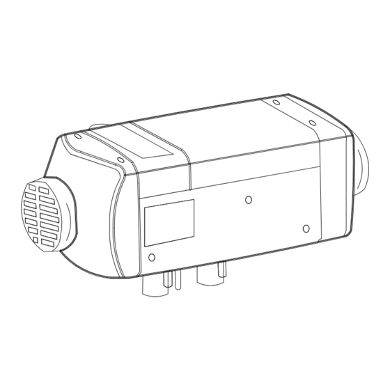
PRODUCT INTRODUCTION The main parts of the Aussie Traveller 12 2kW Diesel Heater (hereinafter referred to as ‘the heater’) is a small fuel furnace controlled by a single-chip micro-processor. Its furnace body (the heat exchanger) is located in the hood shaped case, which serves as an independent air passage. -
Page 4: Structure
TECHNICAL DATA (cont.) STRUCTURE: The structure of the main body as shown: 1. Air Fan 2. E.C.U. 3. Air Motor 4. Bottom Case 5. Insulating Bush 6. Heat Exchanger INTERNAL STRUCTURE: 1. Heat exchanger 2. Gasket 1 (4 hole) 3. Combustion chamber 4. -
Page 5: Heater Cases
TECHNICAL DATA (cont.) The heat exchanger is made of die cast aluminium with radiating fins around and at the rear end. The combustion tube is located inside the heat exchanger, and the burner assembly is fixed on the front end of the combustion tube. -
Page 6: Installation
INSTALLATION The kit includes everything necessary for a standard installation. 1. Main Heater Body 13. Exhaust Pipe 2. Control Unit (with accessory plug) 14. Muffler 3. Main Wiring Harness 15. M6 Nut & Washer (x4) 4. To Power Supply 16. Fuel Pump 5. -
Page 7: Installation Of The Main Heater Body
For the ease of servicing, fault finding and air flow it’s recommended that the main body is placed in an area with easy access. Illustration below shows the minimum distances required, in millimetres, on the Aussie Traveller 12V 2kW Diesel Heater. -
Page 8: Angle Of Installation
INSTALLATION (cont.) ANGLE OF INSTALLATION: The angle of installation is shown in figure below. Ensure you do not exceed the inclination angle or normal operation will be affected. After installation, make sure there is no friction between the fan and other nearby parts to ensure smooth operation and make sure the heater label is clearly visible for ease of maintenance in the future. -
Page 9: Installation Of Combustion Air Pipe & Exhaust
INSTALLATION (cont.) INSTALLATION OF COMBUSTION AIR PIPE & EXHAUST: The combustion air inlet pipe sucks in fresh air from outside of the vehicle and the exhaust discharges fumes outside of the vehicle. Measures must be taken to avoid the fumes from re-entering the vehicle. The pipes should exit at the bottom of the vehicle, ensuring that the openings are far enough away from any splashing water or dirt that can clog them. -
Page 10: Installation Of Fuel Lines
INSTALLATION (cont.) INSTALLATION OF FUEL LINES: 500-1200mm 2000-6800mm 1. Fuel Tank 6. Fuel Filter A. Blue Plastic Fuel Line 2. Fuel Standpipe 7. Fuel Pump B. Clear Plastic Fuel Line 3. Fuel line connector hose clip 8. Damper 4. Fuel Line 9. -
Page 11: Fuel Standpipe
INSTALLATION (cont.) INSTALLATION OF FUEL LINES (cont.): The fuel pump’s outlet should tilt upward at an angle between 15˚-35˚ (as shown on previous page). Only use the fuel line provided, ensure the pipe is placed away from any possible debris and avoid any sagging in the line. Make sure the fuel line does not flow downward toward the fuel pump. -
Page 12: Wiring Diagram
INSTALLATION (cont.) WIRING DIAGRAM: 1300 663 868 | enquiries@aussietraveller.com.au | aussietraveller.com.au BRISBANE SHOWROOM: 11-15 Oasis Court, Clontarf QLD 4019 | MELBOURNE SHOWROOM: 235 Barry Road, Campbellfield VIC 3061 More information https://www.caravansplus.com.au... -
Page 13: Ecu Connections
INSTALLATION (cont.) WIRING DIAGRAM (cont.): The previous page shows the wiring diagram for the heater. The wires of the main heater have been made into bundles. They can be laid according to the positions of various components and should be fixed to the proper locations. -
Page 14: Controller Installation
CONTROLLER INSTALLATION • The control switch must be installed in the vehicle in accordance with the corresponding technical specifications for vehicle control. SAFETY INFORMATION • Find a suitable mounting surface within the driver’s field of vision to fix the control switch. •... -
Page 15: Warranty Statement
Warranty will commence at the time the final retail customer makes payment for the Product to the wholesale purchaser. 3. If the Product is purchased directly from Aussie Traveller for use by final retail customer and not to be on sold in any way, the Warranty will commence at the time of the original purchase. - Page 16 If such inspection and testing find no defect in the Product, the final retail customer must pay Aussie Traveller’s usual costs of service work and testing. The final retail customer must bear the cost of the transport of the Product to and from Aussie Traveller or the authorised repair agent, and all insurance of the Product.
Need help?
Do you have a question about the 266210001 and is the answer not in the manual?
Questions and answers