Table of Contents
Advertisement
Advertisement
Table of Contents

Subscribe to Our Youtube Channel
Summary of Contents for Bai Institch-i5
- Page 1 Institch-i5 Electric Control System Operation Instruction...
-
Page 2: Table Of Contents
Content Controller Setting Preparation Language Pattern management 10-11 Time How to Input patterns Statistics How to output patterns Test 45-46 Letter embroidery 14-16 How to test machine head's board 47-48 How to embroider letters Machine settings 49-52 Pattern division Trimming setting 53-54 How to divide patterns Thread breakage setting... -
Page 3: Controller
Controller Touchable Screen USB Inset Start / Stop Button Contents Description Touchable Screen High brightness LCD display and touch screen. USB Insert USB insert for patterns input and output. Start / Stop Button Click button to start and stop embroidery. Tips:... -
Page 4: Preparation
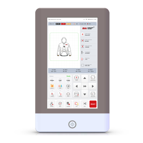
Preparation 1.Machine Information 2.Status Interface 3.Pattern Preview 4.Pattern Information 5.Coordinate Display 6.Function Entrance 7.Common Function 1. Machine Information Contents Description Signal intensity. USB connection status. Time Change time display method in setting page. Get PDF Manual From www.ibaima.com... - Page 5 Preparation 2. Status Interface Contents Description Current needle position. If “00”,it is “No Needle”.Turn the color change motor knob by hand until screen shows any number but "00". Color display:After choose colors for pattern, will show here. • 1 is last color. •...
- Page 6 Preparation 4. Pattern Information Contents Description Pattern’s name and format. Pattern’s width. Pattern’s height. Completed stitches / Total titches. Completed colors / Total colors. Frame’s type and area. 5. Pattern Information Contents Description (1) Coordinate display of pattern. • Pattern’s width is -X plus +X values. •...
- Page 7 Preparation 6. Function Entrance Contents Description This section provides all the functions of preparation work before embroidery. Working status: 1. Ready. 2. Embroidery. 3. Break. 4. Stop. Pattern selection, input, output, division, combination, and deletion. ❖ Detailed introduction:P10 Rotating, Mirroring, Arraying, etc. on the pattern. ❖...
- Page 8 Preparation Contents Description Set offset point: When make appliqué , press it to set the stop point after going out of the frame. 1. Move the embroidery frame to the specified position. 2. Click the set offset key. 3. Click OK. When no offset point is set, the highest point of the current embroidery frame is automatically defaulted as the offset point.
- Page 9 Preparation Contents Description Move the position of the pattern in frame. speed selection key. • • High speed move Low speed move 7. Common Function Contents Description Set machine parameters. Main axis 100° key. • You can see the degree of main axis in the embroidery information area.
-
Page 10: Pattern Management
Pattern Management Function Menu Pattern List Function Menu Contents Description Input patterns with USB. • Input the USB, click input key, select the pattern in the USB, click save, and the pattern will be saved in the pattern management. ❖ Detailed introduction:P12 Patterns output to USB. - Page 11 Pattern Management Contents Description Letter embroidery: Click to enter the letter editing interface. ❖ Detailed introduction:P14 Multiple select: Batch import, output and delete patterns. • It is usually used in importing , outputing , and deleting patterns. Delete: Delete the pattern after selecting it. Divide: After selecting the pattern, click to enter the pattern division editing.
-
Page 12: How To Input Patterns
How to Input Patterns Insert USB. Select the patterns to inputted. • The default is multi-selection, you can select multiple patterns at the same time to input together. Click import key Click Tips: Click When inputting, if USB can’t be read, please re-plug or replace USB to input again. -
Page 13: How To Output Patterns
How to Output Patterns Insert USB. Click Tips: If you need to output all patterns, please click directly. Click Tips: When outputting, if USB can’t be read, please re- plug or replace USB to input again. Do not remove the USB until the output is complete to avoid data loss. -
Page 14: Letter Embroidery
Letter Embroidery Contents Description Letter fonts. • Supports 10 fonts, which can be switched by clicking the left and right keys. Keyboard input area. click on the keyboard input area to bring up the numeric keyboard to write letters. Get PDF Manual From www.ibaima.com... - Page 15 Letter Embroidery Contents Description Color change switch. • When close, the pattern has only one color at this time. • When open, each individual letter will have a random color. Letter height adjustment. • Adjustable range 5-100mm. Letter spacing adjustment. •...
- Page 16 Letter Embroidery Stitch Improve Example The default setting is 0mm. • The more the shrinkage of the fabric or the pattern, the bigger stitch improve value will be set. Affected by the fabric used, it needs to be adjusted according to the actual situation. The following is for reference only.
-
Page 17: How To Embroider Letters
How To Embroider Letters Click Edit letters as request. After adjustment, click Click Enter letters Enter Key Get PDF Manual From www.ibaima.com... -
Page 18: Pattern Division
Pattern Division Contents Description Customize the division of stitches. • Input the specific number of stitches, and click the left and right switching keys to divide. Divide the pattern with specific number. • Only the system default number of stitches can be selected for division. -
Page 19: How To Divide Patterns
How To Divide Patterns Click Divide as request After adjustment, click Choose the pattern to be divided Find 2 divided patterns in list Click Tips: Design division is to divide the pattern into two according to the specified number of stitches. After the division , two divided designs will be displayed on the design management interface. - Page 20 Pattern Combination Contents Description The scaling ratio of the pattern in X/Y direction. • The default ratio is 100%, and the adjustable range is 50%-200%. • It can zoom in and out in same proportion by clicking. Adjust the X/Y direction spacing between patterns. Get PDF Manual From www.ibaima.com...
-
Page 21: Pattern Combination
Pattern Combination Contents Description Pattern rotation setting. • Tap to enter a custom rotation angle. • Rotate according to the specified angle and direction: Rotate 0 degrees/Mirror rotate 0 degrees. Rotate 90 degrees/Mirror rotate 90 degrees. Rotate 180 degrees/Mirror rotate 180 degrees. Rotate 270 degrees/Mirror rotate 270 degrees. -
Page 22: How To Combine Patterns
How To Combine Patterns Click save after selection Click Combine patterns as request Click Click save After combination Combined patterns in pattern management list. Select patterns to be combined Up to 4 patterns can be selected for combination. Get PDF Manual From www.ibaima.com... - Page 23 Edit Pattern Contents Description The scaling ratio of the pattern in X/Y direction. • The default ratio is 100%, and the adjustable range is 50%-200%. • It can zoom in and out in same proportion by clicking. Stitch improve: Used to improve embroidery quality, according to different fabrics and patterns size to adjust.
-
Page 24: Edit Pattern
Edit Pattern Contents Description Symmetry mode: Switch between normal symmetry, X symmetry, Y symmetry, and XY symmetry. • Normal symmetry: • X Symmetry: • Y Symmetry: XY Symmetry: • Pattern rotation setting. • Tap to enter a custom rotation angle. • Rotate according to the specified angle and direction: Rotate 0 degrees/Mirror rotate 0 degrees. - Page 25 Edit Pattern Contents Description Y-direction array editing. • Click to enter the desired number of arrays. • Click to adjust spacing of arrays. The spacing is judged according to the origin point of embroidery, recommended that the spacing of the array be larger than that of the pattern’s height. Get PDF Manual From www.ibaima.com...
-
Page 26: How To Edit Pattern
How To Edit Pattern Click Tips: Please use professional design software for more precise editing design request. Edit patterns as needed. Click save after configuration Get PDF Manual From www.ibaima.com... -
Page 27: Color Setting
Color Setting Color Settings Area Needles Color Display Area Contents Description On the left is the color sequence and total number of colors of the pattern. On the right are the actual embroidery thread colors used for each needle. If the color of the needle does not match the embroidery thread used, you can click Back to set the right color. - Page 28 Color Setting Contents Description Appliqué : If add appliqué in the current color, click this key, and the pattern will be added after the current needle number. When embroider this color, it will automatically be out of the frame and stop, waiting for the appliqué to be added. After finishing, start the machine directly to continue embroidery.
-
Page 29: How To Set Colors
How To Set Colors Confirm the total number of colors in the Tips: pattern. Take figure 1 as an example, the pattern has 12 colors, then you need to set from 01 to the 12th color. Select the corresponding needle number according to the color. -
Page 30: Needle Color Setting
Needle Color Setting Contents Description 1.First select the needle number to be set. 2.Click the color block on the left to select the desired color, and click Save. Please refer to the actual color of the embroidery thread corresponding to the needle. Get PDF Manual From www.ibaima.com... -
Page 31: How To Set Needle Colors
How To Set Needle Colors Select the color of the blocks as desired. Click Click the needle number to be set Click Save after setting Get PDF Manual From www.ibaima.com... -
Page 32: Choose Frame
Choose Frame Contents Description Cap1: For front part of cap. Cap2: For side and back part of cap. Must first select the hat frame, and then install the hat driver when embroider cap! Get PDF Manual From www.ibaima.com... - Page 33 Choose Frame 内容 描述 T1-TMax : Garments hoops. • T1:60*60mm/2.4ʺ* 2.4ʺ • T2:100*100mm/3.9ʺ* 3.9ʺ • T3:120*120mm/4.7ʺ* 4.7ʺ • T4:160*160mm/6.3ʺ* 6.3ʺ • T5:260*260mm/10.2ʺ* 10.2ʺ • Tmax:480*320mm/18.9ʺ* 12.6ʺ Please refer to the actual configuration size of different models for the maximum size of the frame. F : Flat embroidery frame.
-
Page 34: Quickly Add Embroidery Frames
Quickly Add Embroidery Frames Click OK Install hoops in machine Find the left edge of frame. Click size key • Move the direction key to make the No. 1 needle close to the left edge. • After confirming the left edge, click Next. Please pay attention to the control distance (needle No. - Page 35 Quickly Add Embroidery Frames Find the right edge of frame. If confirm to add, click • Move the direction key to make the No. 1 needle close to the right edge. If the data collection is wrong, click Close to re-collect •...
-
Page 36: Track Location
Track Location Contents Description Before embroidery, it is used to confirm the embroidery position of the pattern. • The pattern cannot exceed the embroidery frame. Used with laser positioning, if there is no such device, you can observe the contour area that needle No. 1 walks through. - Page 37 Track Location 内容 描述 Normal trace: Fast tracking along the largest edge of the pattern Outline trace: Stitch tracking on the actual edge of the pattern. • Normal trace first, then outline trace When no laser positioning device, it is Before embroidery, be sure to track and forbidden to press the No.
-
Page 38: Embroidery State
Embroidery State Contents Description Working status display area (waiting, embroidery, thread breakage, completion) Embroidery speed display: Real-time speed/maximum speed set. Speed down / Speed up Get PDF Manual From www.ibaima.com... - Page 39 Embroidery State 内容 描述 Operations such as pattern selection, input, output, division, combination, and deletion. • Same as Ready state. ❖ Detailed introduction:P10 Set the color of the pattern. • Same as Ready state. ❖ Detailed introduction:P27 Embroidery status trace and position: add stitch trace embroidery mode.
-
Page 40: Setting
Setting Contents Description Language : Set the machine language. Time : Set the machine time. Get PDF Manual From www.ibaima.com... - Page 41 Setting 内容 描述 Statistics : Used to view working statistics and clear statistics operations. Test : Used to test whether the sensors, motors, and control boards of the machine are functioning normally. Machine parameters : Used to set machine thread trimming, thread breaking, speed, embroidery frame and other related parameters.
-
Page 42: Language
Language Description The machine supports 17 languages and can be modified as needed. Get PDF Manual From www.ibaima.com... -
Page 43: Time
Time Description Set machine time Get PDF Manual From www.ibaima.com... -
Page 44: Statistics
Statistic Description List data can be cleared by clicking The total data cannot be deleted or changed, and normal test data displayed after the new machine is received. Get PDF Manual From www.ibaima.com... -
Page 45: Test
TEST Contents Description Input signal test. Test whether the X-axis, Y-axis sensor signals, trimming sensor signals are normal. Output signal test. Click test to test whether the thread hooking, trimming, picking , and upper thread clamping are normal. Get PDF Manual From www.ibaima.com... - Page 46 TEST Contents Description Axis test: Test whether the X-axis motor, Y-axis motor, main axis motor, and zero optocoupler are normal. • Main axis 100 degrees: Click the main axis to turn to 100 degrees. • Main axis 178 degrees: Click the main axis to turn to 178 degrees.
-
Page 47: How To Test Machine Head's Board
How To Test Machine Head's Board Observe the central indicator light, if red Click and flashes with the rotation of the roller, it means that the roller inspection optocoupler is normal. If the color of the red alarm indicator remains Click unchanged, it means that the roller detection optocoupler is abnormal. - Page 48 How To Test Machine Head's Board Toggle down the spring by hand to separate spring and iron piece. Observe the indicator light in the center, after the spring is separated from the iron piece indicator light changes from red to green, it means that the spring detection optocoupler is normal.
-
Page 49: Machine Settings
Machine Settings Get PDF Manual From www.ibaima.com... - Page 50 Machine Settings Parameter Name Parameter Description Defaults When set pattern beginning to end continuous embroidery : • Auto Set Start Point If set yes, pattern will embroidery from former stop point. • If set no, pattern will embroidery from the whole origin point. Get PDF Manual From www.ibaima.com...
- Page 51 Machine Settings Parameter Name Parameter Description Defaults Whether return to start point after finished: • Auto Return Start Point If set yes, it will return to start point after finish. • If set no, it will stop at the last one stitch point after finish. Whether the frame automatically shift to the top of the frame after the embroidery is finished.
- Page 52 Machine Settings Parameter Name Parameter Description Defaults Whether to repeat embroidery automatically after the pattern is completed. Repeat Embroidery • If set to "Yes", the embroidery will be repeated. • If Set to "No", the machine will stop. Whether to choose embroidery thick material. •...
-
Page 53: Trimming Setting
Trimming Setting Parameter Name Parameter Description Defaults Amount of jump stitches start trimming or no trimming, the Jump Stitch larger the value is, the thread trimming less frequent. The remaining length of upper thread after thread trimming, Length After Trim the larger the number, the longer the remaining thread. The angle at which the upper thread clamp opens after it is closed Upper Clamp Angle again after startup. - Page 54 Trimming Setting Parameter Name Parameter Description Defaults How many stitches are locked during thread trimming and starting to prevent the thread from falling off after thread Trim Lock Stitch trimming, value The larger the value , the more trim lock stitches during thread trimming and starting. When embroidering thin materials, the length of the lock Trim Lock Length stitch should be large, and when embroidering thick materials, it...
-
Page 55: Thread Breakage Setting
Thread Breakage Setting Parameter Name Parameter Description Defaults Upper thread breakage detection sensitivity. • The larger the value set, the lower the detection sensitivity. Top Thread Broken Test • If set to "no detection", it will not alarm and stop after thread breakage. Get PDF Manual From www.ibaima.com... - Page 56 Thread Breakage Setting Parameter Name Parameter Description Defaults Bottom thread broken detection sensitivity. • When set to "High", the detection sensitivity is high. Bottom Thread Inspect Middle • When set to Medium, the detection sensitivity is medium. • When set to "no detection", it will not alarm and sop after thread breakage.
-
Page 57: Speed Setting
Speed Setting Parameter Name Parameter Description Defaults Auto Speed Down embroidery after specified stitches number. Auto Speed Down Stitch 2.0mm • Set to "2 .0mm", the embroidery will start to slow down when the stitch step exceeds 2mm. Slow down to the specific percentage of current speed when jump stitches continuously. - Page 58 Speed Setting Parameter Name Parameter Description Defaults Speed of main axis at start and stop. Start Main Axis Speed • The more speed set, the longer trimming length. Maximum speed setting of main axis (limited by mechanical parameters) Main Axis Max Speed 1000 •...
-
Page 59: Frame Setting
Frame Setting PX coordinate value Frame angle rounded Frame size in X direction Frame size in Y PY coordinate value direction Description After confirming the size of the embroidery frame and the coordinates of the center position, set the embroidery frame. -
Page 60: Add Frame Manually
Add Frame Manually Put backing fabric Backing fabric Embroidery frame Put backing fabric Measure the center point of the frame and record the dimensions in the X and Y directions (in mm). X Size Center Y Size Find the X center line of the Find the Y center line of the Confirm the center point of frame... - Page 61 Add Frame Manually Install the embroidery frame to the machine. Determine the center point of the frame Find the origin point automatically Click ok. Click Switch to needle 1. Get PDF Manual From www.ibaima.com...
- Page 62 Add Frame Manually Use the direction keys to move the embroidery frame so that needle No. 1 coincides with the center point of the embroidery frame Record the values of PX and PY and fill them in the embroidery frame settings Fill in the values of PX and PY in C1-C5 of the embroidery frame setting.
- Page 63 Add Frame Manually Fill in the recorded X Size, Y Size and circle R values in the embroidery frame settings. • No rounding corners, R set to 0. • The size of input X size and Y size should be 30mm smaller than the actual embroidery frame as a safety distance. R=60 X Size Y Size...
-
Page 64: Wi-Fi
Wi-Fi Description It is used to connect computer and embroidery machine for pattern transmission control. • Install matched Institch-Link software firstly. Get PDF Manual From www.ibaima.com... -
Page 65: Find The Origin
Find the Origin Description The absolute origin is to use the frame limit to detect the absolute position of the embroidery frame, so as to ensure that after an unexpected situation occurs in the middle of embroidery, the power-off recovery embroidery can be used to carry out accurate continuous embroidery. -
Page 66: How To Find The Origin
How To Find the Origin Find The Origin Point Manually Find The Origin Point Automatically Move the embroidery frame to the Click Auto-Origin desired position. Click Ok Click manual-origin Click ok. The embroidery frame automatically finds the absolute position according to the position of the limit photocoupler. -
Page 67: Screen Calibration
Screen Calibration Description After the touch screen is used for a period of time, data drift may occur, resulting in inaccurate key clicks, which can be solved by calibrating the touch screen. When calibrating the touch screen, the clicked position on the screen must be exactly the same as the center of the displayed cross, otherwise it will affect the touch screen operation in the future. -
Page 68: Power-Off Recovery
Power-Off Recovery Description After a sudden power -off in the middle of embroidery, it can automatically return to last stitch and continue embroidery, without worrying about pattern misalignment. Even if the embroidery frame is manually moved after power failure, it can still return to the stop point and continue embroidery. -
Page 69: System
System Contents Description System Info Check the machine name, system version number and other information. System Update Upgrade the new version of the system. Font Upgrade Upgrade the new version of the font. Output Data Setted parameters in the control system can be backed up to the U disk. Input Data Input the backup information from the U disk to the machine. - Page 70 System System Update Steps 1. Input the upgrade package to the root directory of the USB disk. 2. Insert the USB. 3. Click system update. 4. Click OK. 5. Wait for the upgrade to complete and restart automatically. Font Upgrade Steps 1.
-
Page 71: Common Failures And Solutions
Common Failures and Solutions Information Of Failures Reasons Of Failures Solutions Operation head and the multi-function board Check connect cables signal line connect failure Connection Timeout The multi-function board and operation head Replace the multi-function board match failure Multi-function board damaged Replace the multi-function board The touch screen plug connect failure Re-plug in touch screen plug... - Page 72 Common Failures and Solutions Information Of Failures Reasons Of Failures Solutions Check X motor driver and X motor driver over-voltage or over-current protection X motor driver error re-power on Driver damaged Replace driver Check Y motor driver and Y motor driver over-voltage or over-current protection Y motor driver error re-power on...
Need help?
Do you have a question about the Institch-i5 and is the answer not in the manual?
Questions and answers
como conectar el wifi si el teclado no canbla para los simbolos coimo esto @ !/
To connect Wi-Fi on the Bai Institch-i5, you need to install the matched Institch-Link software first. If the keyboard does not type symbols like @ and !, try using an alternative input method such as copying and pasting the required symbols or using a different device to configure the connection.
This answer is automatically generated