Table of Contents
Advertisement
Quick Links
Advertisement
Table of Contents

Summary of Contents for OYO STEPPER CL86
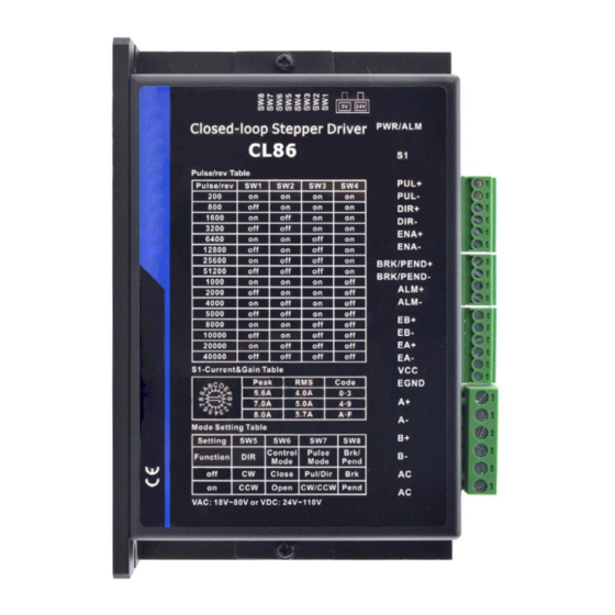
- Page 1 User Manual CL86 (V4.0) Closed Loop Stepper Driver Revision 4.0 Record of Revisions Revision Date Description of Release 1.00 Aug, 2019 Initial Release 4.00 Oct, 2020 Add rotating switch, 5/24V selector switch, brake output. www.oyostepper.com...
-
Page 2: Table Of Contents
CL86(V4.0) Closed Loop Stepper Drive User Manual Table of Content 1. Features ..................................1 2. Specifications .................................1 2.1 Electrical Specifications ............................. 1 2.2 Environment .................................1 2.3 Mechanical Specifications ..........................2 2.4 Heat Dissipation ..............................2 3. Connections and LED Indication ..........................3 3.1 Control and Digital Output Connections ...................... -
Page 3: Features
CL86(V4.0) Closed Loop Stepper Drive User Manual 1. Features Input voltage 18-80VAC or 24-110VDC No loss of step, No tuning 500 KHz max pulse input frequency Resolutions of 200-51,200 via DIP switches SW1 - SW4 2 out current settings and gain tuning via S1 rotating switch ... -
Page 4: Mechanical Specifications
It is recommended to mount the drive vertically to maximize heat dissipation. Mount a cooling fan nearby if necessary. If multiple CL86 (V4.0) drives are installed, it is suggested to keep a minimal 30mm (12 inches) between two of them. -
Page 5: Connections And Led Indication
CL86(V4.0) Closed Loop Stepper Drive User Manual 3. Connections and LED Indication 3.1 Control and Digital Output Connections Details Pulse and Direction Connection: PUL+ (CW+) (1) Optically isolated, high level 3.5-5V or 24V, low voltage 0-0.5V (2) Maximum 500 KHz input frequency PUL- (CW-) (3) The width of PUL signal is at least 1.0μs, duty cycle is recommended 50%... -
Page 6: Motor Connector
4.2 Selecting Supply Voltage The CL86 (V4.0) is designed to operate within 24 - 110VDC or 18 - 80VAC voltage input. When selecting a power supply, besides voltage from the power supply power line voltage fluctuation and back EMF voltage generated during motor deceleration needs also to be taken into account. -
Page 7: Switch Configurations
CL86(V4.0) Closed Loop Stepper Drive User Manual 5. Switch Configurations 5.1 Rotating Switch Configurations This rotating switch is used to set the peak current of the drive and motion gain, from the motor phase current and application requirements. Peak Current... -
Page 8: Micro Step (Sw1-Sw4)
CL86(V4.0) Closed Loop Stepper Drive User Manual 5.2.1 Micro Step (SW1-SW4) Each CL86 (V4.0) has 16 microstep settings which can be configured through DIP switches SW1, SW2, SW3 and SW4. See the following table for detail. Micro step Pulses/Rev. (for 1.8°motor) -
Page 9: Fault Output Connection
(2) ENA signal is no connected as default, and 6.2 Fault Output Connection When over voltage or over current protection happens, CL86(V4.0) red status LED light will blink and the impedance state between ALM+ and ALM- will change (from low to high or high to low depending on configuration) and can thus be detected. -
Page 10: Sequence Chart Of Control Signals
CL86(V4.0) Closed Loop Stepper Drive User Manual Figure 7:Brake output connection 7. Sequence Chart of Control Signals In order to avoid some fault operations and deviations, PUL, DIR and ENA should abide by some rules, shown as following diagram: Figure 8: Sequence chart of control signals Remark: t1: ENA must be ahead of DIR by at least 200ms. -
Page 11: Fault Protections & Troubleshooting
CL86(V4.0) Closed Loop Stepper Drive User Manual 8. Fault Protections & Troubleshooting To improve reliability, the drive incorporates some built-in protection features. Blink Sequence wave of red LED Description Trouble shooting time(s) Turn off the power immediately. a) Check wiring is short-circuited or 0 .2 S... - Page 12 CL86(V4.0) Closed Loop Stepper Drive User Manual Many of the problems that affect motion control systems can be traced to electrical noise, controller software errors, or mistake in wiring. Symptoms Possible Problems Solutions Connect power supply correctly No power Microstep resolution setting is...
Need help?
Do you have a question about the CL86 and is the answer not in the manual?
Questions and answers