Table of Contents

Summary of Contents for ANTARIS SOLAR AS-03/BPKTR3-F
- Page 1 Installation & Instruction Manual SPLIT SYSTEM of EVI DC Inverter Heat Pump IMPORTANT NOTE: Thank you very much for purchasing our product. Before using your unit, please read this manual carefully and keep it for future reference.
-
Page 2: Table Of Contents
CONTENT Installation & Instruction Manual of........................... 1 EVI DC Inverter Heat Pump............................... 1 1. FOREWORD..................................3 1.1. Read the Manual Before Operation........................3 1.2. The Symbol Description of the Device......................8 1.3. Statement................................8 1.4. Safety Factors..............................8 2. OVER VIEW OF THE UNIT............................11 2.1. - Page 3 5.3.2 Mode:Five modes selection.......................37 5.3.3 Status............................... 38 5.3.4 More ............................... 38 6.MAINTENANCE AND WINTERZING..........................41 6.1.Maintenance................................41 6.2Winterizing................................41...
-
Page 4: Foreword
1. FOREWORD 1.1. Read the Manual Before Operation WARNING Do not use means to accelerate the defrosting process or to clean, other than those recommended by the manufacturer.The appliance shall be stored in a room without continuously operating ignition sources (for example: open flames, an operating gas appliance or an operating electric heater). - Page 5 No ignition sources No person carrying out work in relation to a refrigeration system which involves exposing any pipe work that contains or has contained flammable refrigerant shall use any sources of ignition in such a manner that it may lead to the risk of fire or explosion. All possible ignition sources, including cigarette smoking, should be kept sufficiently far away from the site of installation, repairing, removing and disposal, during which flammable refrigerant can possibly be released to the surrounding space.
- Page 6 Ensure that the apparatus is mounted securely. Ensure that seals or sealing materials have not degraded to the point that they no longer serve the purpose of preventing the ingress of flammable atmospheres. Replacement parts shall be in accordance with the manufacturer’s specifications. Repair to intrinsically safe components Do not apply any permanent inductive or capacitance loads to the circuit without ensuring that this will not exceed the permissible voltage and current permitted for the equipment in use.
- Page 7 Removal and evacuation When breaking into the refrigerant circuit to make repairs – or for any other purpose – conventional procedures shall be used. However, it is important that best practice is followed since flammability is a consideration. The following procedure shall be adhered to: Remove refrigerant;...
- Page 8 The recovery process is supervised at all times by a competent person; Recovery equipment and cylinders conform to the appropriate standards. Pump down refrigerant system, if possible. If a vacuum is not possible, make a manifold so that refrigerant can be removed from various parts of the system.
-
Page 9: The Symbol Description Of The Device
1.2. The Symbol Description of the Device The precautions listed here are divided into the following types. They are quite important, so be sure to follow them carefully.Meanings of DANGER, WARNING, CAUTION and NOTE symbols. Symbols Meaning Description The symbol shows that this appliance uses a flammable refrigerant. - Page 10 If the unit is not secure or not installed, it may cause damage. The minimum support weight required for installation is 21g/㎜² If the unit was installed in a closed area or limited space, please consider the size of room and ventilation to prevent suffocation caused by refrigerant leakage.
- Page 11 High speed running fan will result in serious injury. This device is not designed for people who is physically or mentally weak (including children) and who does not have experience and knowledge of heating and cooling system. Unless it is used under direction and supervision of professional technician, or has received training on the using of this unit.
-
Page 12: Over View Of The Unit
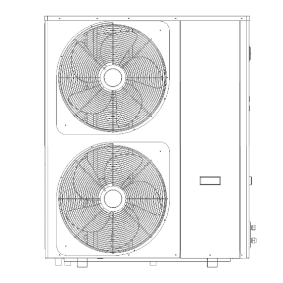
2. OVER VIEW OF THE UNIT 2.1. Dimensions of the Unit AS -03/BPKTR3-F、 AS -04/BPKTR3-F、 AS -03/BPKTR3-F-S、 AS -04/BPKTR3-F-S... - Page 13 AS -05/BPKTR3-F-S、 AS -06/BPKTR3-F-S、 AS -05/BPKTR3-F、 AS -06/BPKTR3-F...
- Page 14 Internal machine size table...
-
Page 15: Main Parts Of The Unit
2.2. Main Parts of the Unit AS-03/BPKTR3-F、AS-04/BPKTR3-F、AS-03/BPKTR3-F-S、AS-04/BPKTR3-F-S Left Net Electric Reactor Back Net ① ⑨ ⑰ Motor Support Compressor Evaporator ② ⑩ ⑱ Fan Blade Chassis Electrical Box ③ ⑪ ⑲ ④ Fan Motor ⑫ Shut-off valve ⑳ Electric control board ㉑... - Page 16 AS-05/BPKTR3-F-S、AS-06/BPKTR3-F-S、AS-05/BPKTR3-F、AS-06/BPKTR3-F Left Net Compressor ⑰ Top Cover ① ⑨ Motor Support Chassis Left Column ② ⑩ ⑱ Fan Motor Right Plate ③ ⑪ Fan Blade Liquid Reservoir ④ ⑫ Air Guide Plate Back Service Plate ⑤ ⑬ ⑥ Mesh Cover ⑭...
- Page 17 Exploded view of main parts of the internal machine Wired controller Outer fixing plate 1 ① ⑦ Water pump Fixed plate 2 ② ⑧ Front panel Water pump ③ ⑨ Plate Heat Exchanger Right panel ④ ⑩ Left panel Outer fixing plate 2 ⑤...
-
Page 18: Parameter Of The Unit
2.3. Parameter of the Unit AS -05/BPKTR3-F AS -06/BPKTR3-F Model AS -03/BPKTR3-F AS -04/BPKTR3-F Power Supply V/Ph/Hz 220-240~/50 220-240~/50 380-415/3N~/50 380-415/3N~/50 Max. Heating 18.6 Capacity 4.48 4.47 Heating Capacity Heating1 4.0/9.1 5.3/12 6.6/15 8.2/18.6 Min./Max. Heating power Input 0.727/2.02 0.97/2.68 1.2/3.33 1.5/4.16 Min./Max. - Page 19 Refrigerant Type - Compressor Twin Rotary -1 Twin Rotary -1 Twin Rotary -1 Twin Rotary -1 Quantity/System Quantity Airflow m³/h 3000 3300 6000 6500 Rated power Plate Heat Plate Heat Plate Heat Plate Heat Type Exchanger Exchanger Exchanger Exchanger Water Side Heat Water Pressure...
- Page 20 Model -03/BPKTR3-F-S AS-04/BPKTR3-F-S AS-05/BPKTR3-F AS-06/BPKTR3-F 220-240V~/50 220-240V~/50 Power Supply 380-415/3N~/50 380-415/3N~/50 V/Ph/Hz Max. Heating 18.6 Capacity 4.48 4.47 Heating Capacity Heating1 4.0/9.1 5.3/12 6.6/15 8.2/18.6 Min./Max. Heating power Input 0.727/2.02 0.97/2.68 1.2/3.33 1.5/4.16 Min./Max. COP Min./Max. 4.5/5.5 4.48/5.46 4.5/5.5 4.47/5.45 Max.
- Page 21 Quantity Airflow m³/h 3000 3300 6000 6500 Rated power Plate Heat Plate Heat Plate Heat Plate Heat Type Exchanger Exchanger Exchanger Exchanger Water Side Water Pressure Heat Drop Exchanger Piping inch G1" G1" G1" G1" Connection Allowable Min./Rated./Max. m³/h 0.95/1.6/1.8 1.3/2.1/2.4 1.5/2.6/3.0 1.9/3.2/3.9...
-
Page 22: Installation And Connection
3. INSTALLATION AND CONNECTION WARNING: The heat pump must be installed by a professional team. The users are not qualified to install by themselves, otherwise the heat pump might be damaged and risky for users’ safety. This section is provided for information purposes only and must be checked and adapted if necessary according to the actual installation conditions. - Page 23 If necessary, the unit may be raised by using suitable mounting pads designed to support its weight. Check that the unit is properly ventilated, that the air outlet is not facing the windows of neighbouring buildings and that the exhaust air cannot return. In addition, provide sufficient space around the unit for servicing and maintenance operations.
-
Page 24: Installation Layout
3.2.3. Installation Layout Notice: Flexible connection between unit and circulating water pipe can prevent vibration from unit to water pipe. The gate valve must be installed at the inlet/outlet of the unit. When the pressure test is completed after the installation of the end of the water system, the gate valve shall be closed for pressure test. -
Page 25: Electrical Installation
3.2.4. Electrical Installation To function safely and maintain the integrity of your electrical system, the unit must be connected to a general electricity supply in accordance with the following regulations: Upstream, the general electricity supply must be protected by a 30mA differential switch. The heat pump must be connected to a suitable D-curve circuit breaker in accordance with current standards and regulations in the country where the system is installed. -
Page 26: Trial After Installation
3.3. Trial After Installation WARNING:Please check all the wiring carefully before turning on the heat pump. 3.3.1. Inspection Before Trial Running Before running test, confirm below items and write √ in block; Correct unit installation Power supply voltage is the same as unit rated voltage ... -
Page 27: Remote Controller Operation Guidance
4. REMOTE CONTROLLER OPERATION GUIDANCE 4.1 Interface Overview There are a total of 5 physical keys in the interface: Switch( ), Query( ), Up( ), Down( ), Setting( ), Mode( ). Note:1)If there is no keystroke beyond the screen saver time, it will enter the Screen Saver Interface. -
Page 28: Icon Of Noun
4.2 Icon of Noun 1.Glossary (1) Running state: it indicates the current operating state of the unit, including standy, start, run, and stop. (2) Running mode: it indicates the current operating mode of the unit, including refrigeration, heating, hot water, heating + hot water, refrigeration + hot water, etc. (3) Unit state:it indicates the current state of the unit, including anti-freezing, defrosting, preheating, etc. -
Page 29: Main Interface
4.3 Main Interface NOTE: In this chapter and the following chapters, the operation interface is described by physical keys!!! After power on the display turn into the Main Interface automatically. In other interfaces, you could press the “Query” key back to the main interface step by step. The fault icon is hidden when the unit has no fault. -
Page 30: Current Fault Interface
4.4 Current Fault Interface Press “Query” key to enter the query menu interface. You could press “Up” or “Down” key to select “Current Failure” option, press “Set” key to enter. Operating instruction: (1) Press the “Query” key to return to the Query Menu Interface. (2) Press the “Setting”... -
Page 31: Version Query Interface
4.6 Version Query Interface Press “Query” key to enter the Query Menu Interface. You could press “Up” or “Down” key to select “Version Query” option, and press “Set” key to enter. Operating instruction: (1) Press the “Query” key to return to the Query Menu Interface. (2) Press the “Up”... -
Page 32: Date And Time Interface
4.8 Date and Time Interface Press the “Setting” key to enter the Settings Menu Interface. You could press the “Up” or “Down” key to select the “Date and Time” option, and press the “Setting” key to enter. month year hour minute second Operating instruction:... -
Page 33: Password Input Interface
action The power indicator light is Power led on often on when the unit is started Indicate sensitivity automatic wake-up when something or someone gets Sensitivity close to the display. The higher sensitivity, farther the sensing distance. Compensate indoor Indoor temperature ( error between temperature indoor temperature and actual... -
Page 34: User Setting Interface
4.11 User Setting Interface Press the “Setting” key to enter the Settings Menu Interface, you could press the “Up” or “Down” key to select the “User Settings” option, and press the “Settings” key to enter with inputting correct password. Settings description: The parameters that users can set, such as setting User.Set temperature... -
Page 35: App Operating Instructions
(1) Press the “Setting” key to reset WIFI. (2) Distribution network according to the display prompt. 5. APP Operating Instructions 5.1 APP install 5.1.1 Mobile phone scanning code and downloading program 5.1.2 After installation, register and log in... -
Page 36: Network Operation
5.2 Network operation 5.2.1 The controller and mobile phone are under the same "WIFI" network Locate the "WIFI" network in the "Settings" Mobile phone connects to "WIFI" network menu of the remote controller... -
Page 37: Mobile Phone Adding Device
5.2.2 Mobile phone adding device Successfully added Connecting 5.3 APP Interface... -
Page 38: Power On/Off
Click the device name to enter the main interface 5.3.1 Power on/off: ; 5.3.2 Mode:Five modes selection... -
Page 39: Status
5.3.3 Status Query temperature, pressure, electrical parameters, operating conditions, etc 5.3.4 More Setting Scheduler Advance Version... - Page 40 a. Setting:Language switching b.schedule: c. Advanced: Input password: the password is the same as the setting parameters of the remote controller...
- Page 41 Enter password to Historical fault Parameter Setting:14 parameter settings Slide the parameter group up and down, select the group that needs the equipment, and press "Confirm"...
-
Page 42: Maintenance And Winterzing
-Select the set parameter group, -The pull-down menu goes to the submenu. -Click this parameter to change it. -The parameter item cannot be changed when it has a gray bottom. 6.MAINTENANCE AND WINTERZING 6.1.Maintenance WARNING:Before undertaking maintenance work on the unit, ensure that you have disconnected the electrical power supply. - Page 43 “CUT OFF” power supply of the heater before cleaning, examination and repairing When you don’t use: a. Cut off power supply to prevent any machine damage. b. Drain water clear of the machine. !! Important: Unscrew the water nozzle of inlet pipe to let the water flow out. c.
Need help?
Do you have a question about the AS-03/BPKTR3-F and is the answer not in the manual?
Questions and answers