
Summary of Contents for Sensotran SENSOTOX 2
- Page 1 SENSOTOX 2 User Manual Sensotran 2020 EXM-S2 MANUAL_S2_EN v9.1 Pág 0 Version 9.1 April 2024...
- Page 2 This equipment has not been evaluating against the essential safety requirements form the points 1.5.5, 1.5.6 & 1.5.7 from Annex 2 of Directive 2014/34/UE relative to measuring instruments. Use only Sensotran original replacement parts Sensotran 2020 EXM-S2 MANUAL_S2_EN v9.1 Pág 0...
-
Page 3: Table Of Contents
I - Zero calibration ..........................8 II - Span calibration .......................... 10 2.5 Sensor replacement ..........................12 2.6 Advanced Menu ............................. 12 Troubleshooting ..........................18 MODBUS/RS-485 ..........................18 SENSOR STABILIZATION TIME ....................20 Sensotran 2020 EXM-S2 MANUAL_S2_EN v9.1 Pág 0... -
Page 4: Introduction
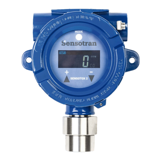
1. INTRODUCTION Sensotox 2 EC uses an electrochemical sensor to detect oxygen and toxic gases. It works with voltages from 12 to 36 V dc with an analogue (4-20 mA) or digital (RS-485, ModBus) output. Sensotox2 is equipped with flameproof enclosure, and this may be blind or have a window with a display for reading the gas concentration, status LEDs and magnetic keys for configuration. -
Page 5: Hazardous Area Approval
Sensotox 2 PID uses a sensor to detect volatile organic compounds (VOCs). It works with voltages from 12 to 36 V dc with an analogue (4- 20 mA) or digital (RS-485, ModBus) output. Sensotox2 is equipped with flameproof enclosure, and this may be blind or have a window with a display for reading the gas concentration, status LEDs and magnetic keys for configuration. -
Page 6: Technical Specifications
Sensor Pressure 0.9 – 1.1 Atm Box pressure Max 50 bar / 10 s 30 V, 2 A normally open. One for alarm 1 and Relay contacts* one for alarm 2. * Ask Sensotran for other possibilities. April 2024 EXM-S2 MANUAL_S2_EN v9.1... -
Page 7: Sensotox2 Ir Specifications
Sensor Pressure 0.9 – 1.1 Atm Box pressure Max 50 bar / 10 s 30 V, 2 A normally open. One for alarm 1 and Relay contacts* one for alarm 2. * Ask Sensotran for other possibilities. April 2024 EXM-S2 MANUAL_S2_EN v9.1... -
Page 8: Sensotox2 Lel Specifications
30 V, 2 A normally open. One for alarm 1 and Relay contacts* one for alarm 2. * Ask Sensotran for other possibilities. The use in atmospheres containing silicones, chlorinated or halogenated compounds and from sulphur may damage the sensor April 2024 EXM-S2 MANUAL_S2_EN v9.1... -
Page 9: Sensotox2 Pid Specifications
Sensor Pressure 0.9 – 1.1 Atm Box pressure Max 50 bar / 10 s 30 V, 2 A normally open. One for alarm 1 and Relay contacts* one for alarm 2. * Ask Sensotran for other possibilities. April 2024 EXM-S2 MANUAL_S2_EN v9.1... -
Page 10: Operation
Once the unit has been installed, leave it running for 24 hours and check it with gas. PHYSICAL DESCRIPTION The design of Sensotox 2 makes it easy to place and connect at a fixed location to monitor gas. April 2024... - Page 11 April 2024 EXM-S2 MANUAL_S2_EN v9.1...
-
Page 12: Installation
3. For European applications, the installation must meet the requirements of EN 60079-14. 2.2.1 Installing Make 2 holes in the mounting surface 126 mm apart. Sensotran 2020 EXM-S2 MANUAL_S2_EN v9.1 Pág 0... -
Page 13: Uninstalling
2.2.2 Uninstalling Before dismantling, make sure that power is disconnected. 1. Unscrew the cover by rotating it anti-clockwise. 2. If the unit has a display, remove the four fixing screws and then the ribbon cable connector of the display. 3. Disconnect the power connectors and communication/relay connectors. -
Page 14: Installing The Unit
2. Connect the Sensotox 2 cables via the connection holes. The pins correspond to the following table: Terminal Cable Pin# Block 1 Common alarm (*) Low Alarm (*) High Alarm / Fault (*) RS485A RS485B Block 2 4-20 mA output... -
Page 15: Earthing Instructions
2.2.5 Earthing instructions External earth connection Crimp 4 mm2 cable into a 4 mm connector. Internal earth Use the same terminal as for the external earth connection. April 2024 EXM-S2 MANUAL_S2_EN v9.1... -
Page 16: Display And User Interface
2.3 Display and User Interface 2.3.1 User interface All Sensotox 2 devices with a window are equipped with four status LEDs, a four-digit LCD display and three magnetic keys [+], [MODE] and [-]. ZERO SPAN FAULT LOW HIGH + Mode - The blind Sensotox 2 have a small seven segments display with three mechanical keys: [+], [MODE] and [-] on the main board. -
Page 17: Magnetic Key
2.3.2 Magnetic key The Sensotox 2 with window has no external keys, but uses the magnet to activate keys inside the unit. Place the magnet over the key to activate the desired button. 2.3.3 Using the magnet Briefly touch the magnet onto the MODE circle or the [+] and [-] triangles. -
Page 18: Display Readout
2.3.5 Display readout In the detectors with window, once the detector goes into read mode, it starts an automatic check for possible faults and alarm conditions. If there is no fault or alarm condition, the green "Ok" LED is activated and the gas concentration is shown. -
Page 19: Calibration
2 should be checked by exposing the sensor to a known concentration of gas over a period of time Sensotox 2 units are calibrated using a two-point calibration process. First, use the "Zero calibration", then the "SPAN calibration" exposing the sensor to a reference gas concentration to establish the second calibration point. -
Page 20: I - Zero Calibration
Sensotox 2 connected to a calibration gas cylinder with an adapter. 2.4.1 Calibration I - Zero calibration 1. Ensure that there are no flammable gases or gases that might interfere with the sensor reading in the area where the detector is located. - Page 21 3. In atmosphere with pollutants, connect the calibration ZERO cylinder to the sensor head of the Sensotox 2 using the calibration adapter and apply the gas flow. 4. Press [+] to start calibration. - On display units: 2ErO The Zero LED will be lit and “...
-
Page 22: Span Calibration
Reading Mode II - Span calibration 1. Connect the SPAN calibration cylinder to the sensor Sensotox 2 head using the calibration adapter and applying a flow of gas. Tip: To accede the Span Calibration from reading display, press [MODE]. When “... - Page 23 Tip: To exit the calibration menu, press [-] to return the normal reading. Note: It is not necessary to exit from the calibration menu manually. After 60 seconds of inactivity, the Sensotox 2 automatically returns to the normal reading. 2. Press [+] to start calibration.
-
Page 24: Sensor Replacement
Sensotox 2 will return to the normal reading. 6. Turn off the Span calibration gas cylinder and remove it. On the event of a failed calibration, call Sensotran Service at +34 93 478 58 42 or follow the Sensor Replacement Instructions 2.5 Sensor replacement... -
Page 25: Advanced Menu
Reading Screen Press and hold 1 second Press and hold 1 second MODE Press and hold 1 second CALu Edit Parameter MODE Advanced Menu (Next Parameter) After 60 seconds without activity, detector returns to actual reading screen. April 2024 EXM-S2 MANUAL_S2_EN v9.1... - Page 26 Advanced Menu Display Setting CALu Span Calibration value Correction Factor (for LEL & VOC only) Low Alarm Hi Alarm Instrument ID Transmission Speed bAUd (19200, 9600 or 4800) Lite Backlight Aout Analogue output (4 / 20 mA) • To modify a setting, press [MODE] until desired value appears.
- Page 27 CALu Edit Setting MODE Edit Setting MODE Edit Setting MODE Edit Setting MODE Edit Setting MODE bAUd Edit Setting MODE Aout Edit Setting MODE Actual Reading April 2024 EXM-S2 MANUAL_S2_EN v9.1...
- Page 28 How to edit and modify Settings. Increased Value Decreased Value MODE (Setting non (Setting modified) modified) (Blinking) MODE SAuE Value April 2024 EXM-S2 MANUAL_S2_EN v9.1...
- Page 29 4-20 mA Analogue Output adjustment. Aout Edit Setting MODE Edit Setting MODE April 2024 EXM-S2 MANUAL_S2_EN v9.1...
-
Page 30: Troubleshooting
Service Centre. 4. MODBUS/RS-485 Retrieving gas concentration data from Sensotox 2 through RS-485. The Sensotox 2 communicates by means of MODBUS RTU. All monitors provide 4-byte register value. Note: Gas concentration is the only value that can be retrieved. As example 34 hex = 52 decimal. - Page 31 2. Message Frame/Communication Procedure Sensotox 2 only support function code 0x03 (read holding registers), which only supports the “Get Reading Value” from the detector. Requesting Message: Device Function Register Register Quantity of Quantity of Address Code Address Address Registers Registers...
-
Page 32: Sensor Stabilization Time
SENSOR STABILIZATION TIME The stabilization time of each sensor varies depending on the gas and the manufacturer. Below is a table with the different sensors and the stabilization time recommended by the manufacturer: 001 – O2, Range: 0-25% 24 hours 002 –... - Page 33 08820 El Prat de Llobregat Rev. 2 Barcelona (Spain) Copy Authorised by: Tel. +34 93 478 5842 Marc Delgado www.sensotran.com EC DECLARATION OF CONFORMITY SENSOTOX 2 Declaration number: 20017001 (SX-XXX-XX) SENSOTOX BE (SB-XXX-XX) Description: Fixed gas detector Use: Toxic, flammable, oxygen, CO2 & VOC monitoring on hazardous area.
- Page 34 Bergueda 1 Planta 2 Oficina A3 Mas Blau Industrial Area El Prat de Llobregat BARCELONA – SPAIN Tel. +34 93 478 5842 sensotran@sensotran.com April 2024 EXM-S2 MANUAL_S2_EN v9.1...
Need help?
Do you have a question about the SENSOTOX 2 and is the answer not in the manual?
Questions and answers