Advertisement
Quick Links
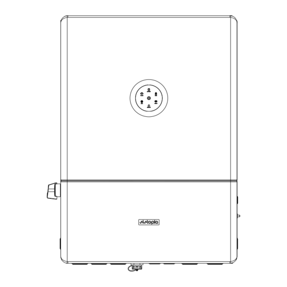
H2-(5K-12K)-(S3,S4)-US Inverter Quick Installation Guide
For more information, refer to the inverter user manual.
1. Checking installation ways and gaps
19.213"
(488mm)
27.362"
(695mm)
2. Installing the inverter
1.
Determine the installation position and drill holes on the wall.
Note: Reserve enough distance at the inverter bottom for installing the metal cable conduits.
2.
Use four M6 expansion bolts to fix the mounting plate to the wall.
15.984"
(406 mm)
0.315"
0.315"
(φ8 mm)
(φ8 mm)
3.937"
0.433"
(100 mm)
(11 mm)
21.378"
(543 mm)
3.
Mount the support frame to the inverter. Install two M5 screws on each side of the inverter.
4.
Install one M5 screw on each side of the inverter.
V1.1
7.697"
(198.5mm)
15.984"
(406 mm)
0.315"
8 mm)
3.937"
(100 mm)
M5*14 mm
1.2-1.5 N·m
3. Installing the SBU
Install the SBU between the grid and the inverter. Connect cables to the grid and loads. For details, refer to the SBU user manual.
4. Installing the battery
Install the battery. For details, refer to the battery user manual.
Warning: On one battery, do NOT connect its positive port (BAT+) to its negative port (BAT-). This will short-circuit this battery, causing serious
battery damage.
Note: For regulation compliance, you can install a battery isolator ≥70A near the inverter, except that you are using the Eletopia B2 battery
model which has a built-in DC isolator in its high-voltage box unit: B2-7.3-HV5, B2-14.6-HV5, or B2-21.9-HV5.
5. Opening the wiring compartment of the inverter
1.
Use the Allen Wrench to press down four locks on both sides of the inverter. Then, remove the cover.
2.
Use a flathead tool to remove the Knockout hole fillers. (Inserting into the hole and anti-clock rotation)
1 2 3
6. Assembling the SBU power connection
1.
Insert the 12 V power cables through cable hole D at the bottom of the SBU. For the cable hole location, see section "Cable holes" in the
SBU user manual.
2.
Loosen screws in the high-voltage terminal on the inverter. Connect the 12 V power cables from the SBU to the inverter, as shown below.
Then, tighten the screws.
7. Assembling the AC-side electrical connection
1.
Depending on your inverter, prepare cables according to the below table.
Inverter model
AC breaker
Cable size
H2-5K-S3-US
30 A
10 AWG
H2-8.6K-S4-US
45 A
8 AWG
H2-12K-S4-US
70 A
6 AWG
2.
Strip off the insulation (18-mm/0.71-inch length) of the cable ends.
Grade
Callout
Description
1
PV1-2
2
PV3-4
3
BAT
4
4G/WI-FI; COM2; COM1
5
GRID
4
5
Cable color
Red
Black
From (SBU)
Position 1
Position 4
To (inverter)
Position 9
Position 10
Inverter model
AC breaker
Cable size
H2-7.6K-S3-US
40 A
8 AWG
H2-10K-S4-US
55 A
8 AWG
Description
Value
© 2023 Eletopia. All rights reserved.
Advertisement

Related Manuals for ELETOPIA H2-5K-S3-US

Summary of Contents for ELETOPIA H2-5K-S3-US
- Page 1 (198.5mm) Note: For regulation compliance, you can install a battery isolator ≥70A near the inverter, except that you are using the Eletopia B2 battery model which has a built-in DC isolator in its high-voltage box unit: B2-7.3-HV5, B2-14.6-HV5, or B2-21.9-HV5.
- Page 2 Note: If two meters are connected to the system, the meter address of the inverter side meter should be set to 2. Refer to the meter user manual. Perform system commissioning on the Eletopia App. For details, see the Configuration Instructions. Installer: V1.1...
Need help?
Do you have a question about the H2-5K-S3-US and is the answer not in the manual?
Questions and answers