Table of Contents
Advertisement
Quick Links
Advertisement
Table of Contents

Related Manuals for QS Technology F-86

Summary of Contents for QS Technology F-86
-
Page 2: Table Of Contents
F86 Milling Controller Operation manual CONTENT PART 1 – OVERVIEW OF F86 CONTROLLER ...................4 1.1 INTRODUCTION…………………………………………………………………………………………………………………………………. 5 1.2 BASIC INFORMATION…………………………………………………………………………………………………………………………. 5 1.3 FEATURES………………………………………………………………………………………………………………………………………….. 6 1.4 FUNCTION KEYS………………………………………………………………………………………………………………………………….7 1.5 MAIN SCREEN………………………………………………………………………………………………………………………………….. 13 PART 2 – FUNCTIONS OF CONTROLLER ....................15 2.1 COORDINATE…………………………………………………………………………………………………………………………………… 16 : .......................... - Page 3 F86 Milling Controller Operation manual 2.9.1 D ..............60 MPORT AND XPORT PERATIONS ON THE ONTROLLER 2.9.2 F .................. 63 IRMWARE UPDATE PROCEDURE FOR THE CONTROLLER 2.9.3 S ..........................64 ET DATE AND TIME 2.9.4 A .......................... 66 CCESS ONTROL ETUP P a g e Modified: 08-03-2024...
-
Page 4: Part 1 - Overview Of F86 Controller
F86 Milling Controller Operation manual PART 1 P a g e Modified: 08-03-2024... -
Page 5: Introduction
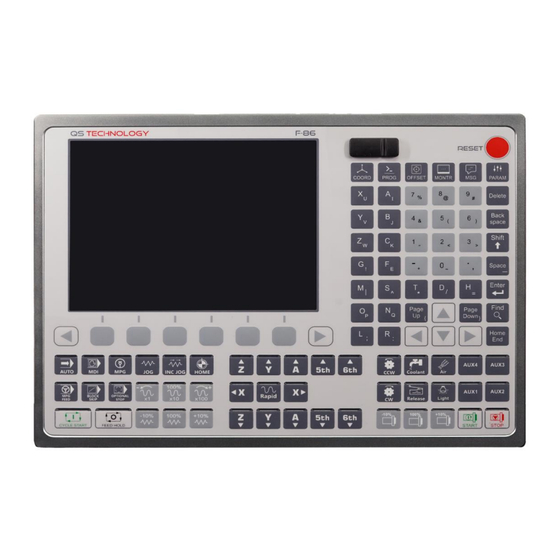
F86 Milling Controller Operation manual 1.1 INTRODUCTION F86 CNC Controller is a new product manufactured and introduced by QS Technology company. This controller can control up to 6 axis. Impressive design, mordern working interface, friendly for machine operators. Furthermore, this controller with numerous hardware and software enhancements and upgrades, will provide smooth user experience along with high-speed processing and stability during operation. -
Page 6: Features
F86 Milling Controller Operation manual 1.3 FEATURES a) COORDINATE a. Devide the coordinate of axis by 2 of REL POS (HALF) b. Zero the coordinate of axis in REL POS (ZERO) c. Zero all the coordinate of axes in REL POS (ZERO ALL) b) PROGRAM a. -
Page 7: Function Keys
F86 Milling Controller Operation manual 1.4 FUNCTION KEYS MÔ TẢ CÁC PHÍM CHỨC NĂNG USB port and RESET button Access to COORDINATE screen Access to PROGRAM screen Access to OFFSET screen Access to MONITOR screen P a g e Modified: 08-03-2024... - Page 8 F86 Milling Controller Operation manual Access to PARAMETER screen Delete 1 object Delete 1 charater Combine with another key to create character, symbol Create blank space Confirm Find an object Move the apostrophe to the end of page Move page down Move page up P a g e Modified: 08-03-2024...
- Page 9 F86 Milling Controller Operation manual Move up, down, left, right Number keys, symbol Selection keys and change page button Access to AUTO function Access to MDI function Switch to use MPG handwheel P a g e Modified: 08-03-2024...
- Page 10 F86 Milling Controller Operation manual Switch to JOG mode Switch to INC JOG mode Move axis to home position Switch to MPG Feed Active BOCK SKIP function Active OPTIONAL STOP function Decrease the RAPID speed (G00) Select movement X1 of MPG Increase the RAPID speed (G00) up to 100% Select movement X10 of MPG...
- Page 11 F86 Milling Controller Operation manual Increase the JOG s[eed (G01) up to 100% Increase 10% the JOG speed (G01) JOG buttons and movement of axes Rotate the tool center in clockwise Active water coolant Active air pressure Rotate the cool center in counter clockwise Turn on the switch to exit of axis traversal...
- Page 12 F86 Milling Controller Operation manual Control the percentage of spindle speed Expand function keys ON/OFF the spindle SAFETY CAUTION 1. The operator must reading this operation manual before using this controller to avoid the error and have a best experience about product. The operator must clearly understand the features of all function keys, values, and parameters of the controller.
-
Page 13: Main Screen
F86 Milling Controller Operation manual 1.5 MAIN SCREEN NOTE: 1. Screen display name. 2. Date and time display bar. 3. Running program name. 4. Active mode. Values (Cutting speed/ Spindle speed/ ..) for comparison during programming and in practice. a. Absolute: Absolute coordinate b. - Page 14 F86 Milling Controller Operation manual Feedrate/Act.Feed: Programming (Feedrate) and actual (Act.Feed) cutting speed Spindle/Act.Spin: Programming (Spindle) and actual (Act.Spin) spindle speed CMDT/Spi: Tool call (CMD T) and spindle tool name (Spi) Machine activity % display a. Spindle: Displays the spindle's active b.
-
Page 15: Part 2 - Functions Of Controller
F86 Milling Controller Operation manual PART 2 15 | P a g e Modified: 08-03-2024... -
Page 16: Coordinate
F86 Milling Controller Operation manual 2.1 COORDINATE • On the coordinate page, the operator can view and understand the machine's operating information and coordinate systems, including: Absolute coordinate system (ASBSOLUTE), Relative coordinate system (RELATIVE), Distance to go Features in the coordinate system: •... -
Page 17: Operation Instructions
F86 Milling Controller Operation manual Operation instructions: 2.1.1 Full-screen zoom translation Step 1: On the main screen interface, press on the COORDINATE function button to access the coordinate page. Step 2: Then press the FULL SCREEN function button to zoom to full screen. 17 | P a g e Modified: 08-03-2024... -
Page 18: Dividing The Axis Coordinate By 2 In The Relative Coordinate System (Half)
F86 Milling Controller Operation manual Step 3: Press the SWITCH function button to switch to other coordinate pages such as (Machine POS, ABS POS, … ). 2.1.2 Dividing the axis coordinate by 2 in the relative coordinate system (HALF) Step 1: Select the axis you want to halve the coordinate by entering the corresponding character key on the control panel. -
Page 19: Regarding The "0" Coordinate Of The Specified Axis In The Relative Coordinate System (Zero)
F86 Milling Controller Operation manual Step 2: Then press the HALF button. The coordinate of the selected axis will be divided by 2. 2.1.3 Regarding the "0" coordinate of the specified axis in the relative coordinate system (ZERO) Step 1: Select the axis you want to reset to "0". -
Page 20: Regarding The "0" Coordinate Of All Axes (Zero All)
F86 Milling Controller Operation manual Step 2: Then click the ZERO function button. The coordinate will now return to the value "0". 2.1.4 Regarding the "0" coordinate of all axes (ZERO ALL) Step 1: The operator navigates to the relative coordinate screen (REL POS). 20 | P a g e Modified: 08-03-2024... -
Page 21: Program Screen
F86 Milling Controller Operation manual Step 2: Then, they press the ZERO ALL button. At this point, the coordinates of all axes will be reset to "0". 2.2 PROGRAM SCREEN • The PROGRAM is a tool that allows operators to store, edit, and process data and programs. -
Page 22: Data Copy Operation To The Controller
F86 Milling Controller Operation manual Features of the Program Screen • EXECUTE: Executes the program. • NEW FILE: Creates a new file. • OPEN FILE: Opens a file. • GO TO LINE: Moves to the specified line of code. • SEARCH: Searches for an object in the program. •... - Page 23 F86 Milling Controller Operation manual Step 2: Press the OPEN FILE button to access the controller's memory. Step 3: Connect the USB peripheral device to the controller. 23 | P a g e Modified: 08-03-2024...
- Page 24 F86 Milling Controller Operation manual Step 4: Select the program/data from the USB peripheral device. Step 5: Then the operator presses the COPY button. The data will be copied from the USB peripheral device to the controller's memory. 24 | P a g e Modified: 08-03-2024...
-
Page 25: Executing A Program
F86 Milling Controller Operation manual 2.2.2 Executing a program Step 1: After accessing the PROGRAM editing screen, the operator presses the OPEN FILE button to access the controller's memory. Step 2: The operator selects the program to be executed and clicks the OPEN FILE button. 25 | P a g e Modified: 08-03-2024... - Page 26 F86 Milling Controller Operation manual Step 3: The operator then presses the EXECUTE button to execute the program. Step 4: At this time, the controller will automatically switch to the MONITOR screen. Note: After executed the working program, the operator need to check the program, relative value before start the machining process.
-
Page 27: Move To The Specified Command Line
F86 Milling Controller Operation manual 2.2.3 Move to the specified command line Step 1: From the program function screen, the operator presses the right arrow button to move to the next function page. Step 2: Press the GO TO LINE function button. 27 | P a g e Modified: 08-03-2024... - Page 28 F86 Milling Controller Operation manual Step 3: Enter the line number you want to move to and click the GO TO button. Step 4: Verify the line you just moved to. 28 | P a g e Modified: 08-03-2024...
-
Page 29: Search For An Object In The Program
F86 Milling Controller Operation manual 2.2.4 Search for an object in the program Step 1: On the editing screen interface, click the SEARCH function button. Step 2: Enter the name of the object you want to find in the program, then click the SEARCH button. -
Page 30: Replace An Object In The Program
F86 Milling Controller Operation manual Step 3: Verify the object you have found. 2.2.5 Replace an object in the program Step 1: On the program screen, press the REPLACE button. 30 | P a g e Modified: 08-03-2024... - Page 31 F86 Milling Controller Operation manual Step 2: Enter the name of the object you want to replace in SEARCH WHAT, enter the replacement content for the found object, press REPLACE to replace one object with the new content, press REPLACE ALL to replace all objects with the new content. Step 3: Verify the objects after the content has been replaced.
-
Page 32: Command Line Deletion Operation
F86 Milling Controller Operation manual 2.2.6 Command Line Deletion Operation Step 1: On the program interface, press the DELETE LINE button. Step 2: Select the command line you want to delete. Then, press the DELETE LINE button. 32 | P a g e Modified: 08-03-2024... - Page 33 F86 Milling Controller Operation manual Step 3: The command line will now be deleted. Note: Note: In case of accidental deletion by the operator and the need to undo the action, The operator should click the left arrow button to navigate back, A pop-up window will appear asking the operator to confirm whether they want to save the program.
-
Page 34: Copying A Command Line To A Designated Location
F86 Milling Controller Operation manual 2.2.7 Copying a command line to a designated location Step 1: From the editing interface, click the right arrow button to navigate to the next page. Step 2: Select the command line you want to copy and click the COPY FROM button. 34 | P a g e Modified: 08-03-2024... - Page 35 F86 Milling Controller Operation manual Step 3: Navigate to the desired location for copying and press the COPY TO button. Step 4: Press the PASTE button to paste the command line. 35 | P a g e Modified: 08-03-2024...
-
Page 36: Edit Program Directly
F86 Milling Controller Operation manual 2.2.8 Edit program directly Step 1: Navigate to the desired location for editing within the program interface. Step 2: The operator edits the program by using the character, symbol keys on the control panel. To save the edited result, press the left arrow key. At this time, a notification will be displayed on the screen asking you if you want to save the the program or not. -
Page 37: Offset Parameter Setting
F86 Milling Controller Operation manual Note: Using the SHIFT key + 1 key that has a symbol will create that symbol. Example: --------------------------------------------------------------------------------- 2.3 2.3 OFFSET PARAMETER SETTING 1. This is where the operator can set the parameters of the workpiece as well as the height and diameter of the cutting tool. -
Page 38: Direct Coordinate Entry
F86 Milling Controller Operation manual Note: • The F54 controller provides users with 6 coordinate systems, including G54, G55, G57, G58 and G59, as well as 18 extended workpiece coordinate systems from G59.1 (G54P7) to G59.12 (G54P18). --------------------------------------------------------------------------------- OPERATING INSTRUCTIONS 2.3.1 Direct coordinate entry Step 1: Access the OFFSET function... - Page 39 F86 Milling Controller Operation manual Step 2: The operator needs to select the coordinate system they want to enter coordinates in using the arrow keys (up/down/left/right). Step 3: Then use the alphanumeric keys (letters/numbers) to enter the value. Step 4: Finally, after entering the necessary value, the operator presses the ENTER key to confirm.
-
Page 40: Quick Assign Machine Coordinates To The Specified Coordinate System
F86 Milling Controller Operation manual 2.3.2 Quick assign machine coordinates to the specified coordinate system Step 1: After entering the OFFSET function, select the coordinate system. Then select the axis to which you want to assign the coordinates. Finally, press the APPLY MACH function button. -
Page 41: Quick Assign Center Coordinates To The Specified Coordinate System
F86 Milling Controller Operation manual Step 3: Recheck the coordinates just assigned from the machine coordinate system. 2.3.3 Quick assign center coordinates to the specified coordinate system Step 1: After entering the OFFSET function, select the coordinate system. Then select the axis to which you want to assign the coordinates. - Page 42 F86 Milling Controller Operation manual Step 2: Press the SELECTED AXIS button to assign the center axis coordinates to the specified axis coordinate system. Select ALL AXIS to assign all values from the center coordinate system to the specified coordinate system. Step 3: Recheck the coordinates just assigned from the center coordinate system.
-
Page 43: Quick Centering Methods Using 4 Points For Square And Rectangular Blanks
F86 Milling Controller Operation manual 2.3.4 Quick Centering Methods Using 4 Points for Square and Rectangular Blanks Step 1: From the OFFSET interface screen, select the MIDDLE FUNCTION function box. Step 2: Set up the coordinate points (Px1, Px2, Py1, Py2) as shown in the figure. 43 | P a g e Modified: 08-03-2024... -
Page 44: Quick Centering Method Using 3 Points For Circular Blanks
F86 Milling Controller Operation manual Step 3: At this point, the center coordinates will be automatically calculated and displayed at the coordinate points Pxm and Pym. 2.3.5 Quick Centering Method Using 3 Points for Circular Blanks Step 1: From the coordinate center setup screen using 4 points, press the SWITCH button to switch to the coordinate center setup screen using 3 points. - Page 45 F86 Milling Controller Operation manual Step 2: At this point, the operator needs to set up the coordinate points (Px1, Px2, Px3, Py1, Py2, Py3) as shown in the figure. Step 3: Then press the CALCULATE button to let the controller calculate the center coordinates.
-
Page 46: Setting Up Cutting Tool Parameters
F86 Milling Controller Operation manual Step 4: At this point, the center coordinates will be automatically calculated and displayed at the coordinate point Pxm, Pym, and the radius will be displayed at R. 2.3.6 Setting up cutting tool parameters (TOOL SET Step 1: From the OFFSET interface screen, select the TOOL SET function button. - Page 47 F86 Milling Controller Operation manual Step 2: Operators can directly input parameters of the machining tool. Similarly, with the WORK SET function, operators can quickly assign machine coordinates and center coordinates to the machining tool parameters. After entering the parameters, press the ENTER button to confirm the settings.
-
Page 48: Monitor
F86 Milling Controller Operation manual 2.4 MONITOR On the monitoring screen, the operator can view and grasp necessary information such • Current machining program name • Active mode • Machine status (running or stopped) • Cutting speed percentage • Spindle speed percentage •... - Page 49 F86 Milling Controller Operation manual Monitoring screen features: • PROGRAM: Quick access to the editing page • 2. SIMULATOR: Access the program simulation feature • 3. MDI: Switch to manual data input mode • 4. AUTO OPTION: Access automatic feature settings •...
- Page 50 F86 Milling Controller Operation manual INSTRUCTIONS 2.4.1 Program simulation: Step 1: From the main screen interface, select the MONITOR function button. Step 2: Then select the SIMULATOR function button 50 | P a g e Modified: 08-03-2024...
- Page 51 F86 Milling Controller Operation manual Step 3: Check the shape of the program after it has been simulated. • Notes: SET WORK: Set workpiece position for simulation 2. AUTO SCALE: Auto-fit simulation to the screen 3. TOOLPATH MODE: Change simulation mode (MILLING 2D/3D, ENGRAVING 2D/3D) 4.
-
Page 52: Manual Data Input (Mdi) Feature
F86 Milling Controller Operation manual 2.4.2 Manual Data Input (MDI) feature Step 1: To switch to MDI mode, the operator must first press the MDI button on the control panel, Then, go to the MONITOR function and select the MDI function box. Step 2: Enter the data from the control panel, then press the OK button. -
Page 53: Auto Option
F86 Milling Controller Operation manual 2.4.3 AUTO OPTION Giải thích: Explain: AUTO OPTION: A feature that assists operators when unexpected issues occur during the machining process, leading to production interruptions. It offers the following functionalities: • Resume from the previously stopped line: This allows the program to resume execution from the exact point where it was interrupted, ensuring a smooth transition and minimizing material wastage. - Page 54 F86 Milling Controller Operation manual • ON/OFF NC CUT: Enable/disable the sub-program initialization feature when restarting the program. 54 | P a g e Modified: 08-03-2024...
-
Page 55: Teach
F86 Milling Controller Operation manual 2.4.4 TEACH Explain: The teach-in function allows users to teach the controller, program macros to improve the machine's performance. 2.4.5 Access the activity history page Explain: From the MONITOR screen interface, press the PART LOG button to access the controller's activity history page. -
Page 56: Error Alarm Monitoring
F86 Milling Controller Operation manual 2.5 ERROR ALARM MONITORING Explain: Operators can monitor the error log, error notifications, and error alarms of the controller. To access the MESSAGE page, press the MESSAGE button from the main interface. Additionally, operators can save the error history for inspection when needed. -
Page 57: Signal Diagnostic Page
F86 Milling Controller Operation manual 2.6 SIGNAL DIAGNOSTIC PAGE The Signal Diagnostic Page allows operators to monitor the system data bits, data registers, and macro variables. Diagnostic Features: • NC BIT: Access the data bit page. • NC REGISTER: Access the register data page. •... -
Page 58: Parameter Page Parameters
F86 Milling Controller Operation manual 2.7 PARAMETER The controller parameter page is a very important page. The operator needs to understand and know the parameters on the controller and absolutely not change them arbitrarily without fully understanding the function of that parameter. Because if the operator arbitrarily changes the parameters without understanding the function, it will lead to the machine malfunctioning, which can be dangerous, reduce the machine's productivity and affect the processing process. -
Page 59: System Features
F86 Milling Controller Operation manual 2.9 SYSTEM FEATURES Operators access the SYSTEM page to configure system changes, load, and export controller data SYSTEM Page Features: • DATA I/O: Import and export data such as parameters, offsets, PLC, and HMI. • FIRMWARE: Update and save device firmware versions. •... -
Page 60: Data Import And Export Operations On The Controller
F86 Milling Controller Operation manual OPERATING INSTRUCTIONS 2.9.1 Data Import and Export Operations on the Controller Explain: To successfully load data into the controller, operators must understand the directory formats. If the directory names or formats are incorrect, the data will not be loaded. •... - Page 61 F86 Milling Controller Operation manual To load data into the controller, the operator must follow these steps: Step 1: Copy the folder containing the data (Macro/PLC/Parameter/Offset) to the USB external device. Step 2: Plug the USB into the controller, then go to the SYSTEM function block. 61 | P a g e Modified: 08-03-2024...
- Page 62 F86 Milling Controller Operation manual Step 3: Select the LOGIN field and enter the user password "1415". Then press the ENTER button. Step 4: Next, select the DATA/IO field and choose the type of data you want to load (Macro/PLC/Parameter/Offset, HMI). 62 | P a g e Modified: 08-03-2024...
-
Page 63: Firmware Update Procedure For The Controller
F86 Milling Controller Operation manual Step 5: Select the IMPORT button to load data or the EXPORT button to export data. Choose the folder containing the data you want to load or store. Finally, select CONFIRM to start loading or exporting data. 2.9.2 Firmware update procedure for the controller Step 1: After logging into the SYSTEM page, select the FIRMWARE function block. -
Page 64: Set Date And Time
F86 Milling Controller Operation manual Step 3: Insert the USB peripheral containing the firmware into the USB slot. Then, select the folder containing the firmware. The controller will automatically detect and select the firmware file. Finally, simply click the CONFIRM button to start the update process. Notes: •... - Page 65 F86 Milling Controller Operation manual Step 1: After logging into the SYSTEM page, click the SYS.INIT function button. Step 2: Press the TIME/DATE function button. Step 3: At this point, the operator only needs to set the time values to match the real time and click on the SET TIME box.
-
Page 66: Access Control Setup
F86 Milling Controller Operation manual 2.9.4 Access Control Setup • Operators access this feature to assign usage permissions to user accounts on the controller. For the management level, assigning permissions helps to ensure the security of the parameters configured on the controller. The checked boxes indicate that the account will have access to those features.
Need help?
Do you have a question about the F-86 and is the answer not in the manual?
Questions and answers