Advertisement
Quick Links
Contents
1 Brief Introduction ............................................................................................. 1
2 Testing and Operation .................................................................................. 10
3 Measurement Techniques ............................................................................42
4 Prevention method of measurement error ............................................ 50
5 Upper Computer Data Application ...........................................................55
6 Precautions ...................................................................................................... 58
7 Repair .................................................................................................................61
Advertisement

Summary of Contents for AWR UT200
-
Page 1: Table Of Contents
Contents 1 Brief Introduction ..................... 1 2 Testing and Operation .................. 10 3 Measurement Techniques ................42 4 Prevention method of measurement error ..........50 5 Upper Computer Data Application ............55 6 Precautions ...................... 58 7 Repair .........................61... -
Page 2: Brief Introduction
Brief Introduction Application Field The thickness gauge adopts the Interface-Echo-Echo ultrasonic measurement principle (IE), which is suitable for the measurement of the thickness of various materials in which the ultrasonic can propagate at a constant speed and get the reflection from the back. At the same time, it is also equipped with a test function to check whether the precious metals are adulterated and identify the purity. - Page 3 Working Theory The principle of ultrasonic thickness measurement is similar to that of light wave measurement. The ultrasonic pulse emitted by the probe reaches the measured object and propagates in the object. When it reaches the material interface, it is reflected back to the probe. The thickness of the measured material is determined by accurately measuring the time of ultrasonic propagation in the material.
- Page 4 Basic Cast Iron Precision High Temperature Main Unit 1 pc Type Type Type Type Probe 1 pc 5MHz 2MHz 7MHz Standard Standard Standard High Temperature Couplant 1 pc Coupling Coupling Coupling Coupling AA battery 2 pcs √ √ √ √ Instruction Manual Guarantee Card √...
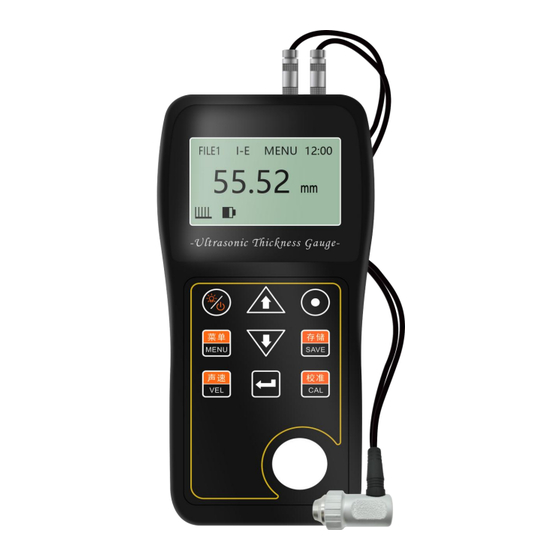
- Page 5 1.4 Name of each part of the instrument 1.4.1 See Figure 1 below Fig. 1 Main View of Through-coating Thickness Gauge...
- Page 6 1.4.2 Schematic diagram of keyboard...
- Page 7 1.5 Instrument Features Three measurement modes, P-E I-E and TEST, are adopted to accurately measure the thickness; I-E mode enables the gauge to measure thickness through coating; high precision timing chip and v-path calibration model are adopted, with wide measurement range and high measurement accuracy;...
- Page 8 display, which can be used in various light environments. 1.6 Main functional parameters it has zero calibration, which can automatically correct the system error; if the thickness is known, the sound velocity can be measured back to improve the measurement accuracy; it has the coupling state prompt function to intuitively grasp the ...
- Page 9 1.7 Technical Parameters Basic Type Cast Iron Type High Precision Type High Temperature Type Testing Range(Steel) 1.0~500mm 2.0~500mm 0.85~300mm 4.0~80mm Display Error(<10 mm) ±0.04mm ±0.04mm ±0.04mm ±0.05mm Testing Error(≥10 mm) ±0.4%H mm ±0.4%H mm ±0.4%H mm ±0.4%H mm Testing Frequency 5MHz 2MHz 7.5MHz...
- Page 10 Continuous Working 50 hours (without backlight) time 500 groups of measurement results, including measurement time and sound Data Storage velocity information Auto Power off Automatic shutdown without action for 2 minutes (settable), with switch button Display Content Thickness value, coupling state, electric quantity state, calibration state, sound velocity, time, etc Size 155mm X 68mmX27mm...
-
Page 11: Testing And Operation
Testing and Operation 2.1 Measuring Preparation 1) Insert the probe plug into the host probe socket. Press the key to start the instrument, and the screen display is shown in the following figure:... - Page 12 1. Current document number (five documents in total) 2. Measurement mode (test / PE mode is optional) 3 Menu options (select menu to set instrument parameters and realize relevant functions) 4 System time 5 Sound velocity unit (thickness unit displayed during measurement) 6 Automatic storage flag 7.
- Page 13 "PE" is the principle of pulse reflection ultrasonic measurement, which is applicable to the measurement of the thickness of various materials in which the ultrasonic can propagate at a constant speed and get the reflection from the back. "Test" is to use ultrasonic technology to check whether precious metals are adulterated and identify their purity.
- Page 14 bars, silver bars, gold coins and silver coins. 3) Set probe frequency Press the key to move the cursor to the menu (as shown in the figure below), and press the key to enter the menu. Select "system setting" by pressing the key, and then press to enter the system interface.
- Page 15 Note: the probe frequency setting must be consistent with the probe frequency used, otherwise the measurement accuracy will be affected. Velocity adjustment If the current screen displays the thickness value, press the key to enter the Velocity (sound speed) display, and the screen will display the current velocity Then press the key to cycle and select five common sound speeds.
- Page 16 time you press the key, you can select one common velocity , including fixed steel (5920m / s), gold (3240m / s), silver (3650m / s), platinum (3960m / s), palladium (3070m / s) and a user-defined velocity . When the user-defined sound speed is selected, the velocity value can be adjusted by pressing the key.
- Page 17 object, so the accurate measurement requires the input of accurate sound velocity value. If the sound velocity of the measured object is uncertain, the method in the chapter "sound velocity calibration" can also be used to take a known thickness test block of the same material to measure the sound velocity. In addition, the sound velocity will change with the change of temperature.
- Page 18 that is, the sound speed of the standard test block attached to the thickness gauge; b. Then apply the couplant (coupling agent) to the random test block, couple the probe with the random test block to measure, press the key to start zero calibration after the coupling is good on the screen, and the calibration progress bar is displayed on the screen;...
- Page 19 Thickness measurement First set the sound velocity, then apply the couplant to the measured position, and then couple the probe with the measured material to measure (the fuller the coupling mark grid, the better the coupling effect). The screen will display the thickness of the measured material.
- Page 20 figure below: When the probe is coupled with the tested material, the coupling mark is displayed. If there are less than 5 grids in the coupling flag, the coupling is not good. Note: 1. When the probe leaves the tested part, the "coupling change value" may be measured, and an error value stays on the display screen.
- Page 21 key before the probe is lifted. 2. If there is a large deviation between the measured value and the real value during coupling, it indicates that the instrument has made a wrong judgment on the measured object. Please lift the probe and measure again until the correct value appears.
- Page 22 key to adjust the display value to the actual thickness value, and then press the key to reverse calculate the sound speed. The reverse calculation progress bar appears on the screen, The measured sound speed will be displayed after the reverse calculation of sound speed is successful, and the sound speed will be stored in the current sound speed storage unit.
- Page 23 Language setting The thickness gauge has Chinese, English and Spanish display functions. The function setting steps are as follows: a. Press the key to move the cursor to "menu", as above. b. Press to enter the menu interface. c. Press to select the menu item "system setting"...
- Page 24 e. After selection, press the key to confirm the setting and return to the main interface. Setting measurement units The thickness gauge has two measurement units, metric and English, and its setting steps refer to Section 2.6. Setting the scanning mode The thickness gauge has scanning mode and can be switched on and off.
- Page 25 If the scanning mode is on, as shown in the figure below, "SCN" will be displayed at the bottom of the screen. There is no SCN indication on the screen, indicating that the instrument is in single point measurement mode. In the scanning mode, the thickness measurement is in the real-time display mode.
- Page 26 Setting buzzer Refer to Section 2.6 for setting steps. When the buzzer mode is turned on, a prompt tone will be given when operating the instrument. When the buzzer mode is turned off, the instrument is in a quiet operation state. 2.10 Set flashing alarm Refer to Section 2.6 for setting steps.
- Page 27 Refer to Section 2.6 for setting steps. Before the test, the parameters of the probe shall be set to be consistent with the measured probe parameters before more accurate values can be measured. (refer to Section 2.1 for details) 2.12 Setting recovery recognition settings a.
- Page 28 2.13 Setting sending data to computer Refer to section 2.12 a, b and C for setting steps. Press the key to select the "send data to computer" option, and press the key to complete the setting. After setting, press and exit. This function is optional and can be equipped after contacting the manufacturer.
- Page 29 Refer to section 2.12 a, b and c for setting steps. Press to select the "delete file" option and press complete the deletion function. This function is to delete the contents of the currently selected folder. After setting, press and exit. 2.15 Setting and deleting all data Refer to section 2.12 a, B and C for setting steps.
- Page 30 Press to select the "set contrast" option, and press to enter the adjustment interface. There are 10 levels of contrast settings displayed on this function screen. Users can press key to set the contrast according to their preferences. After setting, press and exit.
- Page 31 The display is shown in the figure below. After setting, press and exit. 2.18 Setting standby time Refer to section 2.12 a, b and c for setting steps. Then press to select the "set standby time" option, and press to enter the adjustment interface. Press the key to adjust the standby time.
- Page 32 standby time can be set to 20 minutes. After setting, press and exit. Note: if the standby time is 00 minutes, the instrument will not shut down automatically 2.19 Version information viewing Refer to section 2.12 a, B and C for setting steps. Then press to select the "version information"...
- Page 33 2.20 Thickness value storage, viewing and deletion The thickness gauge has the function of measuring data storage. The instrument divides the storage unit into 5 files, and each file can store 100 groups of measuring data. Each group of measurement data contains complete measurement information, including thickness value and measurement time.
- Page 34 1. Set storage file a. Press the key to move the cursor to "file I", as shown in the following figure: b. Press the key, the file number is displayed circularly according to file I ~...
- Page 35 file V, and press the key or key to return to the measurement mode. Note: each file can only store 100 groups of data. When it is full, a prompt will be given (the file is full!), You can set other files for storage according to the above steps.
- Page 36 a. When the measurement results are not frozen, press the key for a long time, the "" automatic storage flag is displayed at the bottom of the screen, and the instrument enters the automatic storage mode; b. When each measurement is completed, accompanied by two rings, the measurement results are automatically saved to the current file.
- Page 37 Note: 001 is the serial number of the currently displayed stored data, 007 is the total quantity of the stored data in the current file, 00-01-01 is the measurement date, 21:48 is the measurement time, and 4.00mm is the measurement thickness value. 5920 is the speed of sound used for the measurement.
- Page 38 e. Press to return. 2.21 Backlight The thickness gauge has the function of backlight. In the power on state, press once to turn on the backlight. In the backlight on state, press again to turn off the backlight. 2.22 Test function The thickness gauge develops a test function for testing gold or other precious metals.
- Page 39 a. Press the key to move the cursor to the "test" or "PE" position, press the key to switch and select the "test" mode, and then press the key until the cursor disappears, exit and select to enter the measurement mode, or press enter the measurement mode directly.
- Page 40 b. Press the key to select the material to be tested, including steel, gold, silver, platinum, palladium, and users (press the key to set the sound velocity value by themselves). Then press to set the thickness of the measured material, and press to adjust the value.
- Page 41 If the tested material does not meet the setting requirements, the screen will display as follows, and the key will display red light. 2.23 Shutdown mode...
- Page 42 The thickness gauge has two shutdown modes: automatic shutdown and manual shutdown. It will shut down automatically without any operation for about two minutes. It can be shut down at any time with a long pressing key.
-
Page 43: Measurement Techniques
3 Measurement Techniques 3.1 Cleaning surfaces Before measurement, all dust, dirt and rust on the surface of the measured object shall be removed, and paint and other covers shall be removed. 3.2 Improve roughness requirements Excessively rough surface will cause measurement error and even no reading of the instrument. - Page 44 ideal situation is when the probe axis intersects with the axis of the measured material. Simply put, couple the probe with the measured material, then rotate the probe around the axis of the measured object or move the probe parallel to the axis of the measured object to make the center line of the probe delay block contact with the measured object, and select a stable reading as the accurate thickness of the material.
- Page 45 otherwise it will cause measurement error or no reading display at all. 3.5 Temperature effect of materials The thickness of material and ultrasonic propagation speed are affected by temperature. If the measurement accuracy is high, the test block comparison method can be used, that is, use the test block of the same material to measure under the same temperature conditions, obtain the temperature compensation coefficient, and use this coefficient to correct the measured value of the measured working piece.
- Page 46 than the actual thickness). In this case, it indicates that the material is not suitable for testing with this thickness gauge. 3.7 Reference test block For accurate measurement of different materials under different conditions, the closer the material of the calibration block is to the measured material, the more accurate the measurement is.
- Page 47 uniform measured material and use it as a test block after measuring with a micrometer. For thin materials, when its thickness is close to the lower limit of probe measurement, the test block can be used to determine the accurate lower limit. Do not measure material below the lower limit thickness.
- Page 48 velocity of known materials, but this only approximately replaces some reference test blocks. In some cases, the value in the velocity is different from the actual measurement because of the differences in the physical and chemical conditions of the materials. This method is often used to measure low carbon steel, but it can only be used as a rough measurement.
- Page 49 the material. c. Multi-point measurement method: multiple measurements are carried out within a certain measurement range, and the minimum value is the material thickness value. 3.9 Probe selection Diameter Features Frequency Measuring Allowable contact Model Of Contact Description (MHz) Range(steel)(mm) temperature(℃)...
- Page 50 7M Micro diameter Special use 0.85~300.0 -10~60 probe H2M High Special use 4.0~80.0 -10~310 Temperature probe...
-
Page 51: Prevention Method Of Measurement Error
Prevention method of measurement error Ultra thin materials Using any ultrasonic thickness gauge, when the thickness of the measured material falls below the lower limit of the probe, it will lead to measurement error. If necessary, the minimum limit thickness can be measured by the test block comparison method. - Page 52 thin materials. 4.2 Rust spots, corrosion pits, etc Rust spots and pits on the other surface of the tested material will cause irregular changes in readings, even no readings in extreme cases, and small rust spots are sometimes difficult to find. When a pit is found or suspected, the measurement of this area must be very careful.
- Page 53 4.4 Probe wear The surface of the probe is made of propylene resin. Long term use will increase the roughness and reduce the sensitivity. When the user can determine that the error is caused by this reason, the user can polish the surface of the probe with a small amount of sandpaper or oilstone to make it smooth and ensure parallelism.
- Page 54 layer thickness. Please pay attention to it when using, You can select a sample block from the same batch of measured materials and measure it with a micrometer or caliper to calibrate the instrument. 4.6 Abnormal thickness readings The operator shall have the ability to distinguish abnormal readings. Generally, rust spots, corrosion pits and internal defects of the tested material will cause abnormal readings.
- Page 55 Couplant shall be used in proper amount and coated evenly. It is important to select a suitable kind of coupling agent. When used on smooth material surface, low viscosity coupling agent (such as randomly configured coupling agent, light machine oil, etc.) is very suitable. When used on rough material surfaces, or vertical surfaces and top surfaces, coupling agents with high viscosity (such as glycerin paste, butter, grease, etc.) can be used.
-
Page 56: Upper Computer Data Application
5 Upper Computer Data Application The measurement data of the thickness gauge can be synchronized on the computer , and the thickness data and statistical data can be displayed graphically by group. And the measurement data of the instrument can be exported to XLSX or PDF format. - Page 57 5.2 Update Data When connecting for the first time, the upper computer will synchronize all current measurement data of the lower computer. If the data of the lower computer is updated again, you can manually click [Refresh Data] to synchronize the latest measurement data of the lower computer.
- Page 58 [Language] and [Unit] on the right side can switch the language displayed on the host computer interface and the data unit displayed by the host computer. 5.5 Save Measurement Data As PDF or XLSX Click [Save to PDF] or [Save to XLSX] on the right to select the save directory and save the device measurement data separately for data transfer and printing in other scenarios.
-
Page 59: Precautions
6 Precautions 6.1 Cleaning of test block Since the coupling agent needs to be coated when the random test block is used to test the instrument, please pay attention to rust prevention. Clean the random test block after use. Don't sweat when the temperature is high. If it is not used for a long time, the surface of the random test block shall be coated with a little grease for rust prevention. - Page 60 cleaning, gently wipe it with a small amount of water. 6.3 Probe protection The probe surface is very sensitive to the redrawing of rough surface, so it should be gently pressed in use. When measuring the rough surface, try to reduce the scratch of the probe on the working surface.
- Page 61 follows: Press the button to shut down, open the battery compartment cover and take out the battery. Put the charged No. 7 alkaline battery into the battery compartment (pay attention to the battery polarity) and cover the battery compartment cover. When the instrument is not used for a long time, the battery shall be taken out to avoid battery leakage and corrosion of the instrument.
-
Page 62: Repair
7 Repair 7.1 Testing Problem If the measurement error is too large, please refer to Chapter 4 and 5. If the following problems occur, please contact the maintenance department of our company: a. The instrument is damaged and cannot be measured. b. - Page 63 not disassemble and repair it by yourself. The following accessories and accessories are not included in the warranty: Probe, test block, couplant , battery, casing, window and key film.
- Page 64 Appendix: sound velocity of various materials Media material name Velocity (m/s) aluminium 6320 chromium 6200 copper 4700 gold 3240 iron 5930 lead 2400 magnesium 5750 silver 3600 steel 5900 titanium 5990 zinc 4170...
- Page 65 tungsten 5174 3320 Brass 4280—4700 cast iron 4400—5820 Glass 5260—6120 nylon 2680 stainless steel 5740 Water (20 º C) 1480 glycerol 1920 water glass 2350 Note: the sound velocity in the above table is for reference only, and the actual sound velocity calibration refers to Section 3.1...
- Page 66 User Notice 1、 After purchasing the company's products, please carefully fill in the warranty registration card and affix the user's official seal. Please send the copy of warranty registration card and purchase invoice back to the user service department of the company, or entrust the seller to send it on behalf when purchasing the machine.
- Page 67 according to the company's regulations. 4 、 The "special configuration" (special probe, special software, etc.) outside the finalized products of the company shall be charged according to relevant standards. 5 、 The company cannot provide warranty for any product damage caused by the user's disassembly and assembly of the company's products, improper transportation, storage or incorrect operation according to the "product operation manual", as well as the unauthorized alteration of the warranty card without purchase certificate.
Need help?
Do you have a question about the UT200 and is the answer not in the manual?
Questions and answers