
Related Manuals for YTL YARD COMMANDER

Summary of Contents for YTL YARD COMMANDER
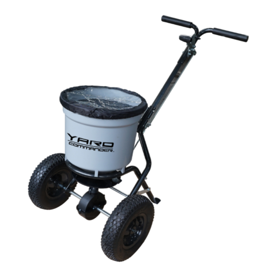
- Page 1 50 LB PUSH SPREADER Instruction & Assembly SAVE THESE INSTRUCTIONS FOR FUTURE REFERENCE REV12122023 SP31503...
-
Page 2: Table Of Contents
Table of Contents General Warnings and Rules................3 Hazard Signal Word Definitions ................4 Controls and Features Identification ..............5 Component & Hardware ..................6 Assembly Instructions ................. 7, 8,9,10,11 Operation Instructions ..................12 Maintenance and Storage & Specification ............13 Parts Drawing &... -
Page 3: General Warnings And Rules
GENERAL WARNINGS READ and UNDERSTAND this manual completely before using Push Spreader. Operator must read and understand all safety and warning information, operating instructions, maintenance and storage instructions before operating this equipment. Failure to properly operate and maintain the push spreader could result in serious injury to the operator or bystanders. -
Page 4: Hazard Signal Word Definitions
Hazard Signal Word Definitions This is the safety alert symbol. It is used to alert you to potential personal injury hazards. Obey all safety messages that follow this symbol to avoid possible injury or death. DANGER indicates an imminently hazardous DANGER situation which, if not avoided, will result in death or serious injury. -
Page 5: Controls And Features Identification
Controls and Features Identification Read this owner’s manual before operating the equipment. Familiarize yourself with the location and function of the controls and features. Save this manual for future reference. 1) Handle – Pushes and moves the spreader easily. 2) Flow Control – Controls the flow of material being spread. 3) Hopper –... -
Page 6: Component & Hardware
CAUTION Read and follow all instructions for assembly and operation. Failure to properly assemble this equipment could result in serious injury to the user or bystanders, or cause equipment damage. PUSH SPREADER COMPONENT PARTS AND ASSEMBLE. Take all parts out of the shipping crate and inspect components to ensure there are no missing pieces before starting to assemble the push spreader. -
Page 7: Assembly Instructions
Assembly Instructions 1. Turn Hopper (#16) upside down and attach Frame (#30) using four screws ST6.3 x 40 (#43). 2. Slide the Impeller (#42) onto the spindle of the Gear Box Assembly (#39). 3. Align the Impeller (#42) with the hole closest to the Gear Box (#39) in the spindle. Then insert Screw M4 x20 (#41) through the hole and fasten tight. - Page 8 1. Slip Inner Axle Bushing (#37) onto the right side of the axle, pushing the Inner Axle Bushing into the Outer Axle Bushing until tight. Attach Wheel (#36) to the right side of the axle by inserting a M5 x 45 bolt (#47) and fastening with Lock Nut M5 (#44). Attach Axle End Cap (#35) by tapping with a wooden or rubber mallet.
- Page 9 1. Flip the hopper over onto it’s wheels. 2. Insert Handle Shaft (#26) between the top ends of the Wheel Assembly Frames (#20). 3. Pass two Bolts M6 x 45 (#11) through Wheel Assembly Frames and Handle Shaft. Slip Pivot and Bracket Assembly (#19) onto protruding bolt ends. Fasten with Lock Nuts M6 (#24).
- Page 10 1. Push the Adjustable Handle (#6, #7) to the lowest position. 2. Insert the upper end of the Control Rod (#25) into the hole at the end of the Adjustable Handle (#6, #7). 3. Take the lower nut (#21) off the bottom end of the Control Rod (#25) and insert rod into the hole in the Pivot and Bracket Assembly (#19).
- Page 11 1. Pull the control lever back to it’s highest point. The three large holes at the bottom of the hopper should match the three holes in the adjustable plate. If they match, do nothing. If they do not match, push the handle down to the lowest position and adjust the positions of the two nuts on the threaded control bar until the three holes match up.
-
Page 12: Operation Instructions
Operation Instructions 1. Determine approximate square footage of area to be covered and estimate amount of material required. 2. Before filling the hopper, make sure the flow control arm is in the off position and the closure plate is shut. 3. -
Page 13: Maintenance And Storage & Specification
Maintenance and Storage WARNING Improper maintenance and storage of the drop spreader may void your warranty. MAINTENANCE After each use clean material out of hopper. • Rinse/dry inside and outside of the spreader after each use. • Periodically check all fasteners for tightness. •... - Page 14 Parts Drawing...
- Page 15 Parts List Ref# Drawing No. Description N570-00012-000 Handle Spacer 9114-06025-DG Carriage Bolt M6x25 9315-08000-DG Teeth Washer Ø8 N570-10000-000 Gauge & Lever Assembly N570-00001-000 Adjust Handle Pole N570-00014-000 Adjust Handle A N570-00015-000 Adjust Handle B 9199-04018-DG Screw ST4.2x18 N510-00016-000 Spacer N510-00019-000 Wing Nut M6 9101-06045-DG Hex Bolt M6x45...
- Page 16 Ref# Drawing No. Description N578-01000-000 Gear Box & Axle Assemble N570-00002-000 Thin Washer 9199-04020-DG Screw M4x20 N510-00003-000 Impeller 9199-06040-DG Screw ST6.3X40 9206-05000-DG Hex Lock Nut M5 N570-00021-000 Cross Brace N570-00004-000 Adjust Connect Rod B 9101-05045-DG Hex Bolt M5X45 9301-06000-DG Flat Washer Ø6 N570-00022-000 Rain Cover 9306-06000-DG...
-
Page 17: Limited Warranty
Limited Warranty Warranty For one year from the date of purchase YTL International will replace for the original purchaser, or repair the spreader. The warranty will not apply to any unit which was not assembled correctly, misused, overloaded or which has been used or operated contrary to our instructions, or which has been repaired or altered by anyone other than an authorized representative.