Table of Contents
Advertisement
Advertisement
Table of Contents

Summary of Contents for Titan Logix FINCH 5332
- Page 1 FINCH 5332 Level Monitor Instrumentation Solutions that just make sense. Head Office Saskatchewan Branch 4130 – 93 Street Box 460, 103 Cenaiko Street Edmonton, AB T6E 5P5 Lampm an, SK S0C 1N0 Toll Free 1-877-462-4085 Web Site www.titanlogix.com E-Mail sales@titanlogix.com...
- Page 2 Titan Logix Corp., we endeavour to design equipment that is simple to use and reliable in its operation, with the aim of satisfying our customers’ needs. Titan Logix Corp. fields of experience include: • Level and Flow Measurement • Transport Instruments •...
- Page 3 Notwithstanding any stipulation of the purchaser to the contrary, all other obligations, representations, warranties or conditions of merchantability, quality or fitness are hereby excluded and Titan Logix Corp. shall not be liable for any loss, costs or damages, of any kind whatsoever, whether consequential, indirect, special or otherwise, arising out of or in connection with the equipment or any defect therein, even if caused by the negligence of Titan Logix Corp., its employees or agents.
-
Page 4: Table Of Contents
Table of Contents Introduction ................... 5 About This Manual ..............5 About the Finch 5332 Level Monitor......... 6 Main Features ................6 Installation ..................7 Environmental ................7 Outline ..................8 Mounting..................8 Interconnection................9 Transmitter Power and SVbus.......... 11 PTO and External Acknowledge........ -
Page 5: Introduction
Introduction About This Manual This instruction manual provides information specific to the Titan Logix Corp. Finch 5332/5332E Level Monitor. Other peripheral equipment should be supplied with its own instruction manual and that manual should be referred to for proper operation of the peripheral equipment. -
Page 6: About The Finch 5332 Level Monitor
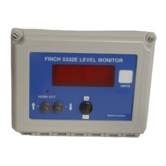
Monitor receives information from the TD80 Level Transmitter and displays it in an easy to read form. The Finch is available in two forms, the Finch 5332 is a compact internal display while the Finch 5332E is a larger external display with a NEMA 4X enclosure. Both units operate in the same manner and will be referred to in this manual as the Finch Display. -
Page 7: Installation
Environmental Choose a mounting location suited to the Finch Display enclosure. The ideal Finch 5332 mounting location is where the: 1. Display sheltered from the weather. 2. Display is out of direct sunlight. 3. Display is easily visible, and within reach of the operator. -
Page 8: Outline
8.5” 4.25” Mounting The Finch 5332 internal display has been designed to mount using a user fabricated bracket or velcro tape. The Finch 5332E external display mounts through the use of mounting feet and 10-32 bolts. Finch 5332E Mounting Dimensions 4.00”... -
Page 9: Interconnection
Interconnection Perform all wiring in accordance with local governing regulations. Please refer to the diagrams below for the location of the configuration jumpers and the I/O terminals on the Finch Display. Finch 5332 Internal Display Decimal Fail Alarm Point Select... - Page 10 Finch 5332E External Display External Connections Base Board in Case Display Board On Door 2 LO Disable Jumper Fill / Fall Jumper Fill Alarm (In = Fall) Relay Select Decimal Fail Alarm Point Select Relay Select Finch 5332/5332E Level Monitor Page 10...
-
Page 11: Transmitter Power And Svbus
Transmitter Power and SVbus Power for the TD80 Level Transmitter is provided through the Finch Display and the level is transmitted to the display through the SVbus. Finch 5332 To Power on Gauge To Gnd On Gauge 8-28 GAUGE GAUGE... -
Page 12: Pto And External Acknowledge
DOWN- GROUND SVBUS DATA LINK GAUGE POWER FILL-NO PTO Switch FILL-NC FILL-COM 8-28 VDC POWER External Acknowledge HH-NO HH-NC HH-COM 8-28 VDC POWER FAIL-NC FAIL COM 8-28 VDC POWER 8-28 VDC POWER GROUND GROUND Finch 5332/5332E Level Monitor Page 12... -
Page 13: High High Alarm Relay Output
This alarm is set up this way for fail safe operation (if the display loses power it will automatically shut down the pump). Finch 5332 Use for a pump... -
Page 14: Fill Alarm Relay Output
This relay is designed for fail safe operation (on when not in an alarm state, off when alarming). This relay is recommended for use in spill protection applications as a Finch 5332/5332E Level Monitor Page 14... - Page 15 Note: This relay is not designed to take the place of proper process supervision when filling the tank. Finch 5332 8-28 To System Fail GAUGE...
-
Page 16: Power Input
DOWN- GROUND SVBUS DATA LINK GAUGE POWER FILL-NO FILL-NC FILL-COM 8-28 VDC POWER HH-NO HH-NC HH-COM 8-28 VDC POWER FAIL-NC FAIL COM 8VDC to 8-28 VDC POWER 8-28 VDC POWER 28VDC GROUND Input GROUND Finch 5332/5332E Level Monitor Page 16... -
Page 17: Operation
Finch Display. Both the 5332 and the 5332E behave exactly the same. For illustration purposes this manual will show the Finch 5332 but everything in this section applies to the Finch 5332E as well. -
Page 18: Calibration
During Start Up the operator may press either of the buttons on the front of the display to enter calibration mode. Upon completion of the self diagnostic cycle the unit will flash CAL for a few second to indicate that it has entered calibration mode. FINCH 5332 LEVEL MONITOR SET FILL OR ACK... -
Page 19: Modes Of Operation
Modes of Operation The following diagram illustrates the relationships between the various modes of operation after the start up sequence and calibration are complete. comm fault MONITOR “ - - - - “ mode state UP / DOWN comm ok key press PTO on PTO off... -
Page 20: Off Mode
The display shows oFF. To exit Off mode the operator needs to press either button on the face plate to enter Display Mode or turn on the PTO to enter Monitor Mode. FINCH 5332 LEVEL MONITOR SET FILL... -
Page 21: Monitor Mode
HH Level through software. After 5 seconds of inactivity the Finch Display will revert to either Display Mode or Monitor Mode depending of the state of the PTO. Disabling the 2 LO Message FINCH 5332 LEVEL MONITOR SET FILL OR ACK... -
Page 22: Alarms
- up - down - up. If the Fill / Fall Alarm and the High High Alarm are both set at the same time they can both be acknowledged at the same time by pressing the External Acknowledge button. Finch 5332/5332E Level Monitor Page 22... -
Page 23: Fail Alarm
Fail Alarm. When the Spill Alarm level is reached the display will flash Spill, set the Spill bit in the Transmitter, and record the alarm in the alarm log. FINCH 5332 LEVEL MONITOR SET FILL... -
Page 24: Error Messages
Contact your distributor strapping table. programming of the strapping Transmitter is not table. suitable for use. E_83 error Restart the system. detected If the problem persists, contact E_84 strapping table your distributor. during operation. Finch 5332/5332E Level Monitor Page 24... - Page 25 Error codes 01, 02, 04, 10, 20, and 40 can be combined if there is more the one error at a time, for example E_26 would be E_02 + E_04 + E20. E_80 to E_84 will not be combined with any other error.
-
Page 26: Troubleshooting
2. Recalibrate. (see Calibration section of this manual) calibration Display show 1. Tank has been over filled, pump out excess fluid immediately. “SPill” 2. Reset the Spill bit in the transmitter. (see Spill Alarm section of this manual) Finch 5332/5332E Level Monitor Page 26... -
Page 27: Specifications
Specifications Finch 5332/5332E Level Monitor Application: For use with Titan Logix Corp. TDR Level Transmitters Power: 8 to 28VDC 1A max. current limited Ambient Temperature: -40ºC to +65ºC (-40ºF to +149ºF) Humidity: 5% to 95% non-condensing Inputs: Up and Down buttons on front of case, external connections for PTO and... -
Page 28: Technical Reference
1 start bit, 8 data bits, 1 stop bit, and no parity. The data transmission rate is 1200 bits per second. The length of the data fields, “r” frames, is fixed at 10 bytes. Finch 5332/5332E Level Monitor Page 28... -
Page 29: Data Field Descriptions
Data Field Descriptions ‘r’ Frame Level Packet used to transmit level from the transmitter to the Finch Display: Byte Example Description ‘r’ Lower case r for reply to a READ command (which was not sent by the Finch Display since the transmitter sends data automatically). This is for compatibility with older systems. -
Page 30: L' Frame
MSB of 16 bit checksum of this data packet, binary ‘C’ LSB of 16 bit checksum of this data packet, binary. Checksum is calculated on all data as 2’s compliment of the actual sum ( 0 - sum). Finch 5332/5332E Level Monitor Page 30... -
Page 31: L' Frame
‘l’ Frame Calibration command data packet send by the level transmitter to Finch Display during Calibration as a reply to 'L' frame: Byte Exampl Description ‘l’ Lower case 'l' for reply to a CAL ‘L’ command (which initially was not issued by Finch Display since the level transmitter gauge sends data automatically) 0x01... - Page 32 Notes Finch 5332/5332E Level Monitor Page 32...
Need help?
Do you have a question about the FINCH 5332 and is the answer not in the manual?
Questions and answers