Advertisement
Quick Links
PHOTOFACT* Fold
er
DUMONT CHASSIS RA-356,
RA-357
DISASSEMBLY
INSTRUCTIONS
CHASSIS REMOVAL
1. Remove 9 push-on type control knobs from front panel
of cabinet.
2. Remove 6 wood screws. Remove rear cover.
3. Remove picture tube socket, speaker leads, HV lead,
yoke plug and antenna plugs.
4. Remove 3 wood screws from bracket at the top rear of
chassis, and 3 wood screws from bracket at the bottom rear
of chassis.
5. Slide chassis from cabinet.
6. Remove 2 speaker nuts. Remove speaker.
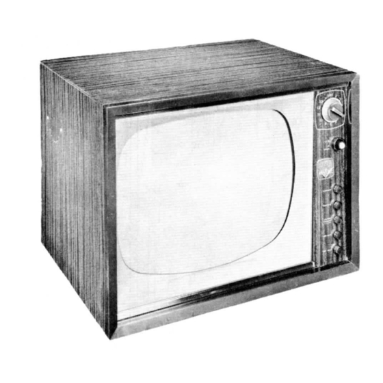
MODEL
"Travis"
CHASSIS
.RA-356
SERVICING IN THE FIELD
TUNER OSCILLATOR ADJUSTMENTS
Touch-up adjustments of the VHF tuner oscillator
circuit may be accomplished by removing the channel
selector and fine tuning knobs.
PICTURE TUBE SAFETY GLASS CLEANING
Remove 5 wood screws holding metal molding at top edge
of the safety glass. Remove molding and safety glass.
Use extreme caution when removing safety glass.
SERVICE ADJUSTMENT LOCATION
See tube placement chart on page 5.
SPECIAL ADJUSTMENTS
A. Picture Stabilizer Adjustment
Adjust the picture stabilizer (R4) for picture with stable
sync. If adjusted too far clockwise picture will have
unstable sync.
B. Dumonltor Control Adjustment
The dumonitor (AGC) control is properly adjusted at the
factory and will normally not require readjustment. To
adjust the AGC control to prevent overloading on very
strong signals the following procedure should be used:
1. Set horizontal hold control for maximum straight-
ness
of
vertical elements of test pattern or
picture near the top of picture.
2. Adjust AGC control until overloading is
eliminated.
3. Switch momentarily to another channel and
back again.
4. If overloading reappears in step 3, readjust AGC
control.
HORIZONTAL OSCILLATOR FIELD ADJUSTMENT
Adjustment of the horizontal oscillator circuit can be made
from the rear panel of the chassis. Set the horizontal hold
control to its mid-range position and adjust the horizontal
stabilizer slug (Bl) until the picture synchronizes horizontally.
SOUND IF DETECTOR BUZZ ADJUSTMENT
To eliminate sound IF detector buzz, adjust the ratio
detector secondary slug (All) located on top of chassis.
FUSES
One fuse is used for LV power supply protection. (For
location see tube placement chart).
CENTERING
Centering is accomplished mechanically by adjusting two
magnetic rings around the neck of the picture tube, located
flush against the deflection yoke. Rotate the two rings
around the neck of the tube until the picture is properly
centered.
70
>
l»
Ui
HOWARD W. SAMS & CO.,
INC.
•
Indianapolis 5, Indiana
"The listing of any available replacement part herein does not constitute In any
case a recommendation, warranty or guaranty by Howard W. Sams & Co., Inc.,
as to the quality and suitability of such replacement part. The numbers of these
parts have been compiled from information furnished to Howard W. Sams & Co.,
Inc., by the manufacturers of the particular t/pe of replacement part listed."
"Reproduction or use, without express permission, of editorial or pictorial con-
G547
tent, in any manner, is prohibited. No patent liability is assumed with respect to
the use of the information contained herein. Copyright 1956 by Howard W.
Sams & Co., Inc., Indianapolis 5, Indiana, U. S. of America. Copyright under in-
ternational Copyright Union. All rights reserved under Inter-American Copyright
Union (1910) by Howard W. Sams & Co., Inc."
Printed in U. S. of America
DATE
10-56
SET 334
FOLDER 5
Advertisement


Need help?
Do you have a question about the TRAVIS and is the answer not in the manual?
Questions and answers