Table of Contents
Advertisement
Quick Links
User's Manual
The content in this manual has been carefully prepared and is believed to be accurate, but no
For
responsibility is assumed for inaccuracies.
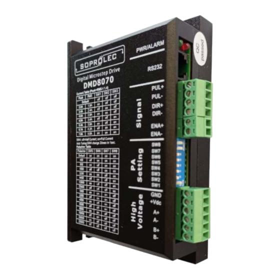
DMD8070
SOPROLEC reserves the right to make changes without further notice to any products herein
to improve reliability, function or design. SOPROLEC does not assume any liability arising out
of the application or use of any product or circuit described herein; neither does it convey any
license under its patent rights of others.
SOPROLEC's general policy does not recommend the use of its products in life support or
Fully Digital Stepping Drive
aircraft applications wherein a failure or malfunction of the product may directly threaten life or
Version 1.0
injury. According to Leadshine's terms and conditions of sales, the user of SOPROLEC's
©2009 All Rights Reserved
products in life support or aircraft applications assumes all risks of such use and indemnifies
Attention: Please read this manual carefully before using the Drive!
SOPROLEC against all damages.
ZAC DE L'EPINE - 72460 SAVIGNE L'EVEQUE
©2009 by SOPROLEC. All Rights Reserved
France T: +33 (0)2 4376 4476
www.soprolec.com
commercial@soprolec.com
Web site:
E-Mail:
Advertisement
Table of Contents

Summary of Contents for SOPROLEC DMD8070
- Page 1 SOPROLEC’s general policy does not recommend the use of its products in life support or Fully Digital Stepping Drive aircraft applications wherein a failure or malfunction of the product may directly threaten life or Version 1.0...
-
Page 2: Table Of Contents
Contents Contents Table of Contents Dynamic current setting ................10 Standstill current setting................10 1. Introduction, Features and Applications..............1 8. Wiring Notes ......................11 Introduction ......................1 9. Typical Connection....................11 Features ......................... 1 10. Sequence Chart of Control Signals ............... 12 Applications ...................... -
Page 3: Introduction, Features And Applications
The Drive must be mounted vertically to maximize heat sink area as shown in the following and so on. Its unique features make the DMD8070 an ideal solution for applications that require both picture. Use forced cooling method to cool the system if necessary. -
Page 4: Operating Environment And Other Specifications
Selecting Active Pulse Edge and Control Signal Mode Avoid dust, oil fog and corrosive gases Environment The DMD8070 supports PUL/DIR and CW/CCW modes and pulse actives at rising or falling edge. 0 ℃ - 40℃ (32℉ - 104℉) Ambient Temperature 40%RH -... -
Page 5: Control Signal Connector (P1) Interface
The DMD8070 can accept differential and single-ended inputs (including open-collector and PNP output). The DMD8070 has 3 optically isolated logic inputs which are located on connector P1 to accept line Drive control signals. These inputs are isolated to minimize or eliminate electrical noises coupled onto the drive control signals. -
Page 6: Connections To 8-Lead Motors
Drive damage. Therefore, it is The DMD8070 can match medium and small size stepping motors (from NEMA frame size 17 to suggested to choose only sufficiently high supply voltage for intended applications, and it is 34) made by SOPROLEC or other motor manufactures around the world. -
Page 7: Selecting Microstep Resolution And Drive Output Current
DMD8070 Digital Stepping Driver Manual V1.0 DMD8070 Digital Stepping Driver Manual V1.0 7. Selecting Microstep Resolution and Drive Output Current 20000 25000 Microstep resolutions and output current are programmable, the former can be set from full-step to 102,400 steps/rev and the latter can be set from 0.5A to 7.0A. See more information about Microstep Current Settings and Output Current Setting in Section 13. -
Page 8: Wiring Notes
(pulse generator). A typical connection is shown as figure 9. 11. Protection Functions To improve reliability, the Drive incorporates some built-in protection functions. The DMD8070 uses one RED LED to indicate what protection has been activated. The periodic time of RED is 3 s (seconds), and how many times the RED turns on indicates what protection has been activated. -
Page 9: Over-Voltage Protection
DMD8070 Digital Stepping Driver Manual V1.0 DMD8070 Digital Stepping Driver Manual V1.0 Problem Symptoms and Possible Causes Over-voltage Protection When power supply voltage exceeds 91±1 VDC, protection will be activated and RED LED will Symptoms Possible Problems turn on twice within each periodic time (3 s). -
Page 10: Professional Tuning Software Protuner
This section will provide an overview of connection and basic setup instructions for Leadshine’s digital stepping Drive DMD8070 using the ProTuner software. These instructions will walk you through the following steps necessary to start up your Drive and motor. This section is intended for setting up the Drive with the ProTuner. - Page 11 DMD8070 Digital Stepping Driver Manual V1.0 DMD8070 Digital Stepping Driver Manual V1.0 Figure 14: Installation folder settings Figure 16: Installation information summarization Figure 15: Shortcut folder setting Figure 17: Installing the ProTuner Set the “Shortcut Folder” in Figure 15 and continue to install the ProTuner by following Figure 16 and Figure 17.
-
Page 12: Connections And Testing
Ø Option Turn on the power supply, the green (Power) LED will light. The DMD8070 has default The user can choose three drop-down menus by clicking “Option”, including Com Config, parameters stored in the Drive. If the system has no hardware and wirings problem, the motor SaveToDrive and Exit. -
Page 13: Com Config Window
DMD8070 Digital Stepping Driver Manual V1.0 DMD8070 Digital Stepping Driver Manual V1.0 Exit: Exit the ProTuner. Com Config Window Figure 21: RS232 communication configuration window Serial Port: Select the serial communication port to which the Drive is connected. The factory default Figure 22: Current Tuning window setting is COM1. - Page 14 However, if the user does not want to tune the current loop after changing a different stepping motor, then Motor auto-identification and parameter auto-configuration technology of the DMD8070 can replace manual tuning the Drive with ProTuner. Just changes SW4 two times in 1 second, and...
-
Page 15: Anti-Resonance Introduction
Step 1: Start the motion test by clicking Start/Stop button. Find an resonance speed by slightly DMD8070 Drive provides robust anti-resonance control to stop the vibrations and maintain moving the slider bar of internal pulse generator back and forth. See Figure 26. - Page 16 The user can choose two drop-down menus by clicking “About”, including Product Information and Contact Us. l Product Information window: Shows some product information about ProTuner. l Contact Us window: Shows some contact information about SOPROLEC. Figure 27: Finishing tuning and download parameter settings to the Drive Ø...
-
Page 17: Appendix
Web: http://www.soprolec.com period of 12 months from shipment out of factory. During the warranty period, SOPROLEC will either, at its option, repair or replace products which proved to be defective. Exclusions...
Need help?
Do you have a question about the DMD8070 and is the answer not in the manual?
Questions and answers