
Related Manuals for Grant Aerona

Summary of Contents for Grant Aerona
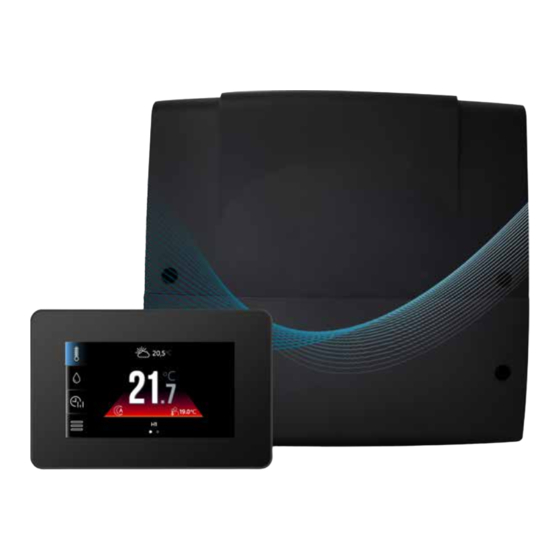
- Page 1 Grant Aerona Smart Heat Pump System Controller Installation & Operation Instructions UK | DOC 0203 | Rev 1.0 | February 2024...
- Page 2 This manual is accurate at the date of printing but will be superseded and should be disregarded if specifications and/or appearances are changed in the interests of continued product improve- ment. However, no responsibility of any kind for any injury, death, loss, damage or delay however caused resulting from the use of this manual can be accepted by Grant Engineering (UK) Limited, the author or others involved in its publication.
-
Page 3: Table Of Contents
Contents INTRODUCTION 10 WI-FI HUB General 10.1 General Safety information 10.2 Connection to wiring centre Information about documentation 10.3 Connection with internet Storage of documentation 10.4 Econet24 Conditions of storage and 11 SERVICING transport 11.1 Component replacement Product contents 11.2 Accessories & spare parts Additional components Customer Support Hub 12 EC DECLARATIONS... -
Page 4: Introduction
The Grant Aerona Smart Controller is intended for controlling installation and is carefully packed with packing materials. a central heating and domestic hot water with a Grant Aerona heat pump. The controller may be used in domestic and light Table 1-1: Product contents commercial applications. -
Page 5: Technical Data
2 Technical Data WIRING CENTRE Table 2-1: Technical Data Grant Aerona Smart Controller - Wiring Centre Power supply 230V AC, 50Hz Controller current consumption 0.4 A Maximum rate current 6 (6) A Protection class IP 20 Ambient Temperature 0 to 50... -
Page 6: Touchscreen Display
TOUCHSCREEN DISPLAY Table 2-2: Technical Data - Touchscreen Display Grant Aerona Smart Controller - Touchscreen Display Power supply 12V DC directly the Wiring centre Touchscreen display current consumption 0.15A Display Touch screen, graphical 480px x 272px Protection class IP 20... -
Page 7: Installation
Similarly, before staring any installation work on the Grant The touchscreen display installation should be done according to Aerona air source heat pump please read the Health and Safety the following guidelines: information given in Section 14 of the Aerona³ installation Detach the mounting plate from the back of the touchscreen instructions. -
Page 8: Wiring Centre
Water Temperature sensor Touchscreen display TEMPERATURE SENSORS Mounting plate cut-away The Smart Controller should be used only with the Grant supplied Screw terminal Outdoor and Water temperature sensors. At least one Water temperature sensor is necessary to activate the controller. -
Page 9: Connecting Pumps
See Appendix B for Installation and operation guidance. functions within the Smart Controller software. ! NOTE ! Grant UK supply the Grant Smart Immersion relay as part of our installation packs. See Appendix D for further guidance on wiring specifics. -
Page 10: System Hydraulics
4 System Hydraulics HYDRAULIC CONNECTIONS HYDRAULIC CONTROLS The Grant Aerona Smart controller can be utilised in a number of 4.3.1 THERMOSTATIC PUMP BLOCKADE ways via the Smart controller configuration creator and settings Thermostatic pump blockade is a hydraulic control feature within configuration. -
Page 11: Hydraulic Connections - Pack P
HYDRAULIC CONNECTIONS - PACK P Grant UK Drawing Number: HPCS-P001S Section 4: System Hydraulics Page 11... -
Page 12: Hydraulic Connections - Pack Q
HYDRAULIC CONNECTIONS - PACK Q Grant UK Drawing Number: HPCS-Q001S Page 12 Section 4: System Hydraulics... -
Page 13: Hydraulic Connections - Pack R
HYDRAULIC CONNECTIONS - PACK R Grant UK Drawing Number: HPCS-R001S Section 4: System Hydraulics Page 13... -
Page 14: Electrical Connections
Electrical components of the planned system are to be connected the wiring centre. to the wiring centre of the Grant Aerona smart controller. Refer to Section 5.4 for wiring centre layout. With the adjustable circuits, mixing needs a water temperature sensor connected to monitor the mixed water entering the circuit to adjust accoridngly. -
Page 15: Wiring Centre Layout
Flow sensor I/O & Ground 33 & 34 Electricity Meter Terminal Set Touchscreen & Thermostat connection terminals (RT1, RT2, RT3) M-BUS Modbus connection to the Aerona Heat pump. G3 Socket Connection port for ecoNET cable Terminal Set +12V, Ground, D+, D- H1-P 13 &... -
Page 16: Electrical Connections - Pack P
ELECTRICAL CONNECTIONS - PACK P Grant UK Drawing Number: HPCS-P001E Notes: Some Neutral and Earth connections have been excluded for clarity. Grant Smart Immersion relay to house 2 live connections. Ensure both are isolated prior to opening housing. Aerona³ Heat Pump... -
Page 17: Electrical Connections - Pack Q
ELECTRICAL CONNECTIONS - PACK Q Grant UK Drawing Number: HPCS-Q001E Notes: Some Neutral and Earth connections have been excluded for clarity. Grant Smart Immersion relay to house 2 live connections. Ensure both are isolated prior to opening housing. Aerona³ ! NOTE ! -
Page 18: Electrical Connections - Pack R
ELECTRICAL CONNECTIONS - PACK R Grant UK Drawing Number: HPCS-R001E Notes: Some Neutral and Earth connections have been excluded for clarity. Grant Smart Immersion relay to house 2 live connections. Ensure both are isolated prior to opening housing. Aerona³ Heat Pump... -
Page 19: System Configuration With Touchscreen Display
Would you like to start configuration? Turn on the Grant Aerona Smart controller via the wiring centre power switch (Refer to Figure 5-1) and allow the software to cycle to the language selection panel. (Refer to Figure 6-1). - Page 20 ! NOTE ! X - Confirm option is not required and proceed. ü - Confirm option is required and proceed. > - Confirm configurable option and proceed. < - Return to previous step in configuration. Page 20 Section 6: System Configuration with Touchscreen Display...
-
Page 21: Weather Compensation
Is Circulation pump for DHW in system? to which they should be wired to on. Refer to Section 5 for This would be enabled if you require the Grant Aerona Smart the terminal blocks and associated devices that they control. -
Page 22: Circuit Control Settings
COMMON SETTINGS 6.3.2 HEATING CURVE ADJUSTMENT The heating curve is adjustable and should be reviewed to ensure After the system has been configured, check and if needed both comfort and economy. amend some common settings within the Heat pump parameters menu via the touchscreen display (Refer to Table 6-2). -
Page 23: Touchscreen Display
7 Touchscreen Display Operation and Settings TOUCHSCREEN DISPLAY The display is a capacitive touch screen and parameters are edited by touching the selected symbol or area on the display screen. 20.5°C ° 19.0°C 19.0°C Ground Floor Figure 7-1: Display home screen example Table 7-1: Touch screen Number Symbol... -
Page 24: Smart Controller Operation
SMART CONTROLLER OPERATION 7.2.1 MAIN HEAT SOURCE 20,5°C The Grant Aerona Smart controller manages the operation of the heat pump by activating or deactivating it according to demand for DHW or the space heating circuits. 7.2.2 HEAT CIRCUITS The Grant Aerona Smart controller can manage the operation of one non-adjustable and up to two adjustable heat circuits. - Page 25 Radiators 7.3.3 CONTROLLER WORK MODE The Grant Aerona Smart Controller work mode of the controller is Underfloor Heating selected by tapping the currently displayed symbol on the main screen in the place where the value of the outdoor temperature is •...
-
Page 26: Legionella Protection
LEGIONELLA PROTECTION TIME SCHEDULES The Grant Aerona Smart controller has the function to provide The Grant Aerona Smart Controller allows for programmable time protection against legionella by executing a scheduled schedules for the Heating Circuit(s), DHW and the Heat pump temperature increase. -
Page 27: Heat Pump Schematic
HEAT PUMP SCHEMATIC 7.5.1 HEATING CIRCUIT SCHEDULE The schedule for the heating circuit(s) controls the specific time The heat pump schematic gives a visual preview of the basic period at which the target day and night temperatures are applied. operating functions of the heat pump such as working status, Flow/return temperatures as well as being able to configure To amend a heating schedule: the operating mode of the heat pump in relation to the system... -
Page 28: Circuit Control
CIRCUIT CONTROL Installation controller The 3 available heating circuits in the Grant Aerona Smart controller are connected and controlled via the following terminals DHW settings within the wiring centre (Refer to section 5). Circulation settings Table 7-10: Circuit terminals Heating circuit... -
Page 29: User Settings Menu
STORED SYSTEM SETTINGS Tap the < button to navigate backwards to the home screen. The Grant Aerona Smart controller can store and recall a default Irrespective of whether pipe sensors are used or not, the space system setting scheme within its memory. -
Page 30: Service Settings - Installer
8 Service Settings - Installer Page 30 Section 8: Service Settings - Installer... -
Page 31: Service Settings
SERVICE SETTINGS Parameter Description Installation control Top level menu function (See previous page) System configuration The creator assists with the configuration of the parameters of the controller when it is started. Depending how you answer creator each question, subsequent questions about the parameters may differ. (Refer to Section 6) Note: All parameters in the creator are available in the service menu. - Page 32 This menu saves and recalls stored defaults applied by the consumer. • Restore default settings - Recall and apply saved default settings. • Save current settings as default - Saves the current setup of the Grant Aerona Smart controller to memory. Page 32 Section 8: Service Settings - Installer...
-
Page 33: Heat Pump Parameters Installer
9 Heat Pump Parameters - Installer 01 Read Only Values 21 Heat Pump Set Points 00 Primary return temp 00 Weather Comp On/Off 01 Compressor frequency 01 Max target Flow Temp 02 Discharge temp 41 Off to On Hys (01 or 02) 03 Power input (Watts) 05 Defrost sensor 31 DHW... - Page 34 Parameter Description 01 Read only Values Heat Pump operating conditions - Displayed information directly from the Heat pump. 21 Heat Pump Set Points 21 00 - Enable/Disable Weather Compensation on Heat Pump (Do not enable) 21 01 - Setting for the Maximum Target Flow temperature (Smart controller adjusts automatically) 21 41 - Hysteresis set point to enable the Heat pump 31 DHW 31 01 - Heat pump priority on DHW demand...
-
Page 35: Wi-Fi Hub
After the power is on, hub requires approx. 1 minute in order to load the operational system. The module will then indicate its The Wi-Fi hub enables the Grant Aerona Smart Controller to condition via the LED. In a connection between hub with a main be accessed and operated remotely via the Internet or app. -
Page 36: Econet24
10.4 ECONET24 Tap the information icon at the bottom. Refer to Figure 10-6. The Wi-Fi hub connects to ecoNET24 via an external server connection. This provides access to the controller via the Internet. User settings You will need an account to log into the the external server, visit www.econet24.com on a web browser to register. -
Page 37: Servicing
Smart Controller Wi-Fi Hub* HPID120 3-Port Diverter valve HPID122 3-Port Valve body** HPID123 Motorised valve actuator** * - supplied as part of Aerona Smart controller kit ** - supplied as part of a Aerona Smart controller installation pack Section 11: Servicing Page 37... -
Page 38: Ec Declarations Of Conformity
Manufacturer declares that the following product conforms to the requirements of the UK Legislation and Regulations as detailed below. The Technical Construction Files are retained at the Manufacturer's location. Product: Grant Smart Controls Model: GRANTSMARTCONKIT In accordance with the following directive(s) or Regulation(s), provided that the products are installed and used in accordance with our instructions: S.I. -
Page 39: Health And Safety Information
Grant Aerona smart controller only. For details of the Health and Safety Information for the heat pump, refer to Section 14 of the Aerona³ installation and servicing instructions supplied. For details of the Health and Safety Information for any other heating appliances being used, refer to the instructions supplied with the appliance. -
Page 40: Guarantee
15 Guarantee You are now the proud owner of an Aerona Smart Controller for Free of charge repairs use with the Grant Aerona Air Source Heat Pump which has been During the two year guarantee period no charge for parts of designed to give years of reliable, trouble free operation. - Page 41 Company. IMPORTANT Grant Engineering (UK) Limited strongly recommends that a Grant Mag-One in-line magnetic filter/s (or equivalent⁵) is fitted in the heating system pipework. This should be installed and regularly serviced in accordance with the filter manufacturer's instructions.
-
Page 42: Appendix A Wired Thermostat
Before reattaching the cover, lead the wire connecting the thermostat with the wiring centre through the hole. The cable must The Grant Wired thermostat is designed to provide individual be recessed into the wall. The cable can not be routed together circuit control via the Grant Aerona Smart Controller. -
Page 43: Pairing
Controller configuration creator for the circuit that the thermostat 1 - No communication with the controller will measure. To pair again you can follow this within the individual circuit settings to re-pair to the Grant Aerona Smart controller. No compatibility of programs •... -
Page 44: Appendix B - Wireless Thermostat And Receiver
Appendix B Wireless Thermostat and Receiver GENERAL The Grant Wireless receiver & thermostat are designed to provide wireless circuit control via the Grant Aerona Smart controller. The thermostat should be installed in a suitable location to monitor the circuit, e.g., First floor hallway, and is designed to maintain a target temperature. -
Page 45: Memory Reset Of The Wireless Receiver
B.3.1 INSERTING OR REPLACING THE BATTERIES • flashing - There is no connection or there is a weak signal and you should choose a different place to install the To insert or replace the battery, remove the back cover of the thermostat or add a signal repeater. -
Page 46: Appendix C - 3-Port Mixer Valve
GENERAL To correctly assemble the 3-Port Mixing valve you will need to: The Grant Aerona Smart controller can manage the temperature Ensure the clutch of the motorised actuator is disengaged of an adjustable circuit with the use of a motorised rotary actuator allowing for free movement with the rotary handle. -
Page 47: Anti-Clockwise Rotation
ANTI-CLOCKWISE ROTATION Slot the Anti-rotation peg in place. C.3.1 ASSEMBLY ! NOTE ! If the Anti-rotation peg is not fitted the motorised actuator will spin in place and not turn the valve as required. Place the motorised actuator onto the valve aligning the drive adaptor and ensure the Anti-rotation peg slots into the actuator body. -
Page 48: Appendix D - Smart Immersion Relay
Ensure both are isolated before removing the of the heat pump and/or Grant Aerona Smart controller. Refer to Figure D-1 for Dual voltage example with external switch. -
Page 49: Appendix E - Smart Flow Sensor
The Smart flow sensor should be fitted on the return to the INSTALLATION heat pump and be after the Grant Mag One filter, observing the The Grant Smart Flow sensor should be installed in a location that calming section required for the inlet. When a suitable location... -
Page 50: Appendix F - How To Videos
QR CODE DESCRIPTION A video guide to provide a clear A video guide for how to access, overview of the Grant Aerona create and copy a schedule for a Smart controller Home screen heating circuit. icons and what they represent. - Page 51 Notes Section X: TBC Page 51...
- Page 52 GRANT ENGINEERING (UK) LIMITED Frankland Road, Blagrove Industrial Estate, Swindon, Wiltshire, SN5 8YG Tel: +44 (0)1380 736920 Fax: +44 (0)1380 736991 Email: info@grantuk.com www.grantuk.com...
Need help?
Do you have a question about the Aerona and is the answer not in the manual?
Questions and answers