Table of Contents
Advertisement
Quick Links
MANUAL / BRUKSANVISNING / GUIDE D'INSTRUCTIONS / BEDIENUNGSANLEITUNG
MANUAL /
MANUAL /
MANUAL /
BRUKSANVISNING / GUIDE D'INSTRUCTIONS / BEDIENUNGSANLEITUNG
BRUKSANVISNING / GUIDE D'INSTRUCTIONS / BEDIENUNGSANLEITUNG
BRUKSANVISNING / GUIDE D'INSTRUCTIONS / BEDIENUNGSANLEITUNG
OriLink®
Monitoring System
Monitoring System
Monitoring System
Monitoring System
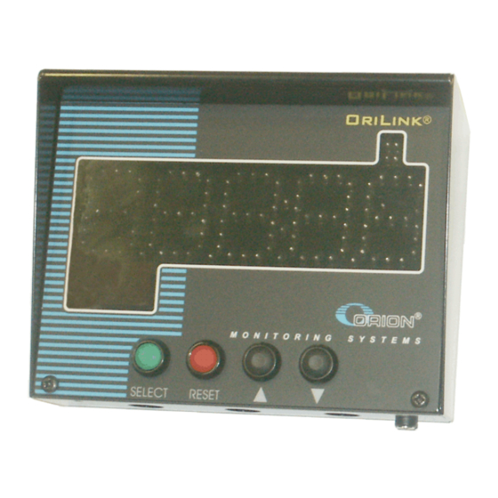
TLED Display, 23429
English Manual for TLED-module 23429, Rev R10, 210326
Advertisement
Table of Contents

Subscribe to Our Youtube Channel
Related Manuals for Alentec & Orion OriLink 23429

Summary of Contents for Alentec & Orion OriLink 23429
- Page 1 MANUAL / MANUAL / MANUAL / MANUAL / BRUKSANVISNING / GUIDE D’INSTRUCTIONS / BEDIENUNGSANLEITUNG BRUKSANVISNING / GUIDE D’INSTRUCTIONS / BEDIENUNGSANLEITUNG BRUKSANVISNING / GUIDE D’INSTRUCTIONS / BEDIENUNGSANLEITUNG BRUKSANVISNING / GUIDE D’INSTRUCTIONS / BEDIENUNGSANLEITUNG OriLink® Monitoring System Monitoring System Monitoring System Monitoring System TLED Display, 23429 English Manual for TLED-module 23429, Rev R10, 210326...
-
Page 2: Table Of Contents
1. INTRODUCTION ................................4 2. MECHANICAL INSTALLATION ..........................5 3. ELECTRICAL INSTALLATION ........................... 5 4. CONFIGURATION IN GENERAL ..........................6 4.1. HECK BEFORE CONFIGURATION 4.2. ECOMMENDATIONS FOR SETTING ADDRESSES 5. CONFIGURATION FROM KEYPAD ........................... 7 5.1. TLED DDRESSING THE 5.2. 5.3. - Page 3 13. FAST MENU CODES..............................25 14. TECHNICAL SPECIFICATION ..........................26 3(26)
-
Page 4: Introduction
Introduction ® Orilink The TLED-module can be connected to an system or together with TCM/TSM modules and used as “stand-alone” tank control. By setting a port of a TCM/TSM module to send its analogue and pump status to the TLED the tank level and pump status is displayed on the TLED. -
Page 5: Mechanical Installation
Mechanical installation The module is mounted on a wall or similar using the four holes in the bottom of the box. Electrical installation The TLED has two 4-pole connectors (G) each marked with A, B, +24 V and Gnd, which are used for the ®... -
Page 6: Configuration In General
Configuration in general ® An OriLink configuration sheet should always be filled or altered during the configuration. NOTE! To obtain technical support a copy of the configuration sheet for the complete installation must be sent to Alentec & Orion AB at Alentec &... -
Page 7: Configuration From Keypad
Configuration from keypad 5.1. Addressing the TLED A new TLED has the address 6000 when delivered. To set an address for a TLED with unknown address press and hold its RESET button for 5 seconds to set a temporary address. Immediately enter Set-Up mode from a keypad and type 0 and then ENTER to get to the Main menu of the TLED, see below. -
Page 8: Set Functional Mask [Tled//Mask]
5.5. Set functional Mask [TLED//Mask] TLED: ‡ The functional mask is used to set basic functions of the TLED display. For now TLED MainMenu only one if it should time-out to show the time or only a “-“ sign. Port: ‡... -
Page 9: Configuration From The Tled Itself
Configuration from the TLED itself Press <SELECT> and <RESET> buttons at the same time will turn it into properties configuration mode. The first parameter shown is the auto scroll interval time. 6.1. Addressing the TLED Scroll to the address parameter using <↑ ↑ ↑ ↑ > or <↓ ↓ ↓ ↓ > buttons. To switch from show to edit mode press <↑... -
Page 10: Setting The Automatic Scroll Interval Time
6.2. Setting the automatic scroll interval time Scroll to the automatic scroll interval time parameter using <↑ ↑ ↑ ↑ > or <↓ ↓ ↓ ↓ > buttons. To switch from show to edit mode press <↑ ↑ ↑ ↑ > and <↓ ↓ ↓ ↓ > buttons at the same time. -
Page 11: Setting The User Scroll Timeout Time
6.3. Setting the user scroll timeout time Scroll to the automatic scroll interval time parameter using <↑ ↑ ↑ ↑ > or <↓ ↓ ↓ ↓ > buttons. To switch from show to edit mode press <↑ ↑ ↑ ↑ > and <↓ ↓ ↓ ↓ > buttons at the same time. -
Page 12: Setting The Automatic Scroll Interval Time
7.2. Setting the automatic scroll interval time Right-click on the TLED graphics and select Properties. Edit the Tank interval time and then click <OK>. 7.3. Setting the user scroll timeout time Right-click on the TLED graphics and select Properties. Edit the Manual scroll timeout and then click <OK>. -
Page 13: Configure The Port
Configure the port A TLED module has a port that can be used to control a dispense point (Reel). LED module has a port that can be used to control a dispense point (Reel). 8.1. Using the on-board dispense point. board dispense point. -
Page 14: Connect A Dispense Point To The Port [Tled//Port/Reelno]
8.2. Connect a dispense point to the port [TLED//Port/ReelNo] TLED: ‡ TLED MainMenu Enter menu [TLED//Port] by scrolling with ↑ ↑ ↑ ↑ or ↓ ↓ ↓ ↓ . Port: ‡ TLED MainMenu At Port: press ENTER. Reel:X ‡ Press ENTER to get the cursor. Set ReelNo ??? Reel:X ‡... -
Page 15: Mask [Tled//Port/Mask]
8.4. Mask [TLED//Port/Mask] How a dispense point should work is controlled by a mask. This Name Value is done by adding the values for the desired functions, in the chart Use PIN-code to the right. Use JOB-no EXAMPLE: At a dispense point you want to use JOB number Use Volume but you do not want to type in a desired volume or a PIN code. -
Page 16: Use External Tank Validation
8.4.8. Use external Tank validation If this is set the dispense point will validate the Requested volume to the specified Tank number at the source specified in DB address. If the “Current Stock” minus the “Requested Volume” is above the specified “Stop Volume”... -
Page 17: Calibrating [Tled//Port/Ppu]
8.6. Calibrating [TLED//Port/PPU] For the TLED module two ways of calibration is possible. 8.6.1. Manual Meters generate pulses according to the amount of fluid that has passed. By opening a dispense point for a certain amount of fluid and then compare how much that has been dispensed (RECORDED) to how much fluid you really received (RECEIVED) you will know if the meter is calibrated or not. -
Page 18: Set Volume Intervals [Tled//Port/Minv] And [Tled//Port/Maxv]
8.6.3. Decimal PPU If a MPDM is flashed with a chip software named MPDM……..(PPUFloat).bin it will support the use of decimal (float number) PPU. Decimal PPU: looks like this “326.54” compared to integer PPU: like 326. To be able to set decimal PPU the keypad must have chip software 1.00.10RC17 and the PC must have the REEL100.ocx version 1.09RC3. -
Page 19: Validation Of Job Number
8.8. Validation of JOB number A TLED dispense point can internally log JOB numbers entered when dispenses is done. If there is a printer/database module in the system or WinDB service is loaded in a PC system dispenses demanded can be validated from a JOB number database, Se also chapter “5.4. -
Page 20: Connect The Dispense Point To A Tank [Tled//Port/Tank]
8.11. Connect the dispense point to a tank [TLED//Port/Tank] TLED: ‡ If there is a printer module in the system or if it is a PC system a dispense point can TLED MainMenu be connected to a database tank, max 8 tanks per PM. In this case the system will be able to check if there is enough oil in the tank and subtract the oil dispensed Port: ‡... -
Page 21: Connecting A Tcm Or Tsm Analogue Tank Sensor To The Tled
10. Connecting a TCM or TSM analogue tank sensor to the TLED A TLED gets the analogue tank level sensor from a TCM (23408) or TSM (23430) based on the properties setting of the TCM/TSM port. 10.1. Example for a TCM port 1 sending tank content to a TLED with address 6000 From either a keypad or a OriLink®... -
Page 22: Setting Up Ports 2, 3 And 4 Of The Same Tcm Will Give These Results
10.2. Setting up ports 2, 3 and 4 of the same TCM will give these results When adding more TCM ports sending tank contents to the TLED they will automatically appear on the TLED. The 4 led’s in the upper right corner of the TLED shows the pump status ON/OFF of the tank 22(26) -
Page 23: How To Remove A Tank From Showing On Atled
10.3. How to remove a tank from showing on a TLED? When you set tanks to send data to a TLED it will automatically appear on the TLED but if you set a TCM/TSM port to stop sending data to the TLED there is no way for the TLED to know if it is removed for good or only temporarily so it will keep on showing the last received data. -
Page 24: Menu Tree
12. Menu tree 24(26) - Page 25 13. Fast Menu codes With a PC, the OriLink® WinTools software and a SIO, you can customize the quick menu that appear when you press ”?”. To do this, assign a name to the menu, a module address and then a code. Password is optional. This code can also be used together with the address after you have typed SETUP followed by the password.
- Page 26 14. Technical specification Printed circuit board Net ports: 2 pcs of OriLink® ports (G) for data communication. Meter input: 1 pcs (A) 32 bit for one or two pulse trains. Breaking or active signal max 50 V. Can detect flow direction and phase errors.
Need help?
Do you have a question about the OriLink 23429 and is the answer not in the manual?
Questions and answers