
Related Manuals for GFA ELEKTROMAT SI 55.12-40,00 Ex


Summary of Contents for GFA ELEKTROMAT SI 55.12-40,00 Ex
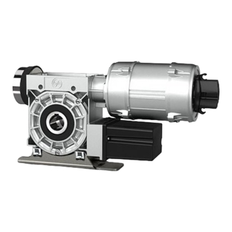
- Page 1 Installation Instructions ELEKTROMAT SI 55.12-40,00 Ex Model: 10005525 00001 -en- Status: 19.10.2023...
- Page 2 GfA ELEKTROMATEN GmbH & Co. KG Wiesenstraße 81 D-40549 Düsseldorf www.gfa-elektromaten.de info@gfa-elektromaten.de...
-
Page 3: Table Of Contents
Table of contents General safety information ....................4 Technical data ........................ 6 Technical data gearbox ....................7 Technical data motor....................... 8 Technical data terminal box .................... 9 Technical data limit switch / switch emergency manual operation ........9 ... -
Page 4: General Safety Information
The safe operation of the product can only be ensured if it is used as specified. Follow the installation instructions. Observe all specifications, especially warnings, when installing the product in the overall system. GfA is not liable for damage resulting from non-observance of the installation instructions. The resulting overall system must be reassessed for its safety in accordance with applicable standards and directives (e.g. - Page 5 instructions for the overall system. We recommend entering the danger area of the system only when the drive unit is at a standstill. Warning - Failure to follow these installation instructions may result in severe injury or death. Please read these instructions before using the product. ...
-
Page 6: Technical Data
2 Technical data Designation Unit Output speed Output torque 550 (240) Output / hollow shaft 40,00 Series SG 85F Limit switch range (maximum revolutions of the output / hollow shaft) Supply voltage 3~ 400 Operating current 2,00 Operating frequency Power factor cos φ 0,70 Safety circuit Degree of protection... -
Page 7: Technical Data Gearbox
Components used Gearbox SG 85F 117.T4 Motor RL 80B4 Terminal box 8146/1041 Limit switch / emergency manual operation switch 07-2511 3 Technical data gearbox Designation Series SG85F-117.T4 Manufacturer Explosion protection II 2G Ex h IIC T4 Gb II 2D Ex h IIIC 130°C Db Max. -
Page 8: Technical Data Motor
4 Technical data motor Designation Type RL 80B4 Manufacturer RAEL MOTORI ELETTRICI S.R.L Explosion protection II 2G Exde IIC T4 Gb II 2D Ex tb IIIC T135° Db Certificate of verification CESI 20 ATEX 040 X Supply voltage 230 / 400 Operating current 3,64 / 2 Operating frequency... -
Page 9: Technical Data Terminal Box
5 Technical data terminal box Designation Type Ex e 8146/1041 Manufacturer Stahl Explosion protection II 2G Ex e II T6 II 2D Ex tD A21 IP 66 T80°C Certificate of verification PTB 01 ATEX 1016 Supply voltage 250 max. 1100 Terminal cross-section Temperature range T6: -20 / +40... -
Page 10: Integrated Safety Brake
7 Integrated safety brake A safety brake is integrated into the gearbox of this ELEKTROMATEN. The safety brake protects against the door dropping due to breakage or wear of the gear teeth. The safety brake works regardless of the mounting position, speed and rotating direction. It is maintenance-free. -
Page 11: Mechanical Installation
8 Mechanical installation Warning – Explosion hazard! Check the atmosphere for explosion hazards before commencing installation tasks. Requirements The permissible loads on walls, mountings, connection and transmission elements must not be exceeded even for maximum holding or locking torque (▶ observe technical data). Connection elements Use self-locking connection Use a screw that precisely... - Page 12 Permissible mounting positions BAGAC0 3 0 0 5 _Z0 0 1 Mounting 2 elongated holes are provided for mounting. BAGAD0 3 0 0 1 _Z0 0 3...
- Page 13 Installation The following descriptions refer to a door which is not further defined. The door manufacturer's specifications must also be observed. Warning – Injury or danger to life possible! Use a lifting device with sufficient load-carrying capacity for installation tasks. Completely grease the door shaft.
- Page 14 Attach the drive unit. BAGAE3 0 0 7 _Z0 0 1 Tighten all connection elements (M12) with a BAGAE0 3 0 1 2 _Z0 0 1 torque of 75 Nm. Install all further connection elements according to the specifications of the door manufacturer.
-
Page 15: Electrical Installation
9 Electrical installation Warning – Danger to life from electrical shock! Disconnect the cables (mains OFF) and check that the supply is off Observe the applicable regulations and standards Ensure proper electrical connection Use suitable tools Carrying out the electrical installation Remove the cover. - Page 16 Protection against overload Motor protection switch / motor protection relay mains operation The "Ex" motor must be protected against overload by means of a motor protection switch or a motor protection relay. Only use motor protection relays with manual reset. Short-circuit protection is also required.
- Page 17 Completing the electrical installation Install cable entries and/or cable glands. In order to achieve the required tightness, the cable glands are equipped with different sealing inserts. They are available for the following cable diameters: 5.5 – 8.0; 8.0 - 10.5 and 10. – 13 mm. Sealing insert and cable diameter must be aligned.
-
Page 18: Limit Switch Setting
10 Limit switch setting The limit switch setting defines the final limit positions OPEN and CLOSE. Requirement The door should open by pressing the OPEN push-button of the control. If the door closes, L1 and L2 must be swapped in a de- energised state. - Page 19 Check the door position: Close the door ① until the cam is released and open it again ② until the OPEN final limit position is reached. The OPEN final limit position can be corrected by following the fine adjustment procedure. Check the door position after each correction.
-
Page 20: Motor Connection
11 Motor connection Bridge rectifier DC-side switching Motor PTC thermistor PTC thermistor PTC thermistor Spring applied brake 12 Limit switch connection Emergency manual operation Terminal strip Emergency OPEN limit switch Emergency CLOSE limit switch OPEN limit switch CLOSE limit switch Additional limit switch Additional limit switch... -
Page 21: Emergency Manual Operation (Emergency Hand Crank)
13 Emergency manual operation (emergency hand crank) The emergency manual operation is designed for opening or closing the door without power supply. Its activation interrupts the control voltage. Electrical operation is no longer possible. Warning – Injuries due to incorrect operation or falling objects! ... - Page 22 Warning – Risk of injury due to uncontrolled movements and falling objects! The drive unit could start up unexpectedly and injure people should a wrong emergency hand crank be used. A wrong crank will drop out of the mounting and injure people.
-
Page 23: Completion Of Commissioning / Testing / Operation
14 Completion of commissioning / testing / operation Check the following components and after that, mount all covers. Gearbox Check drive unit for oil loss (a few drops are not critical). Protect output shaft permanently against corrosion. Oil leakage! Oil leakage may render explosion protection ineffective. Oil maintenance is inadmissible. - Page 24 Mounting Check all mounting elements (consoles, torque brackets, screws, retaining rings etc.) for tightness and impeccable condition. Electric wiring Check connection cables and cables for damage or pinches. Check screw connections for correct seating and electrical contact. Emergency manual operation Function to be checked in a de-energised state.
- Page 25 Entire drive unit Attention – Dust deposits ! Properly remove dust deposits at regular, adequately short intervals, should these be unavoidable due to operation processes. Performed cleaning tasks should be documented. Note! Have the drive checked annually by a specialist. ...
-
Page 26: Disposal
Dispose of old devices properly according to local legal regulations. Return old devices to the return and collection systems available. You can also return GfA products free of charge. Please apply enough postage to the package and mark it as "old devices". - Page 27 EU Declaration of conformity within the meaning of Explosion Protection Directive 2014/34/EU regarding the safe assembly of components Standards applied: GfA ELEKTROMATEN GmbH & Co. KG EN ISO 80079-36:2016 declare under our sole responsibility that the Explosive atmospheres - following modules comply with the above...
- Page 28 EU Declaration of conformity within the meaning of Explosion Protection Directive 2014/34/EU Appendix VIII, "Internal production control" Standards applied: GfA ELEKTROMATEN GmbH & Co. KG EN ISO 80079-36:2016 declare under our sole responsibility that the Explosive atmospheres - following module complies with the above...
-
Page 30: Konformitätserklärung Zubehör
Konformitätserklärung Zubehör... -
Page 32: Declaration Of Incorporation / Declaration Of Conformity
EMC Directive 2014/30/EU within the meaning of RoHS Directive 2011/65/EU The following requirements from Appendix I of GfA ELEKTROMATEN GmbH & Co. KG the Machinery Directive 2006/42/EC are met: 1.1.2, 1.1.3, 1.1.5, 1.2.2, 1.2.3, 1.2.6, 1.3.2,... -
Page 33: Ukca: Declaration Of Incorporation / Declaration Of Conformity
Restriction of the Use of Certain Hazardous Substances in Electrical and Electronic Equipment Regulations 2012 The following requirements from Appendix I of GfA ELEKTROMATEN GmbH & Co. KG the Supply Machinery (Safety) Regulations 2008 declare under our sole responsibility that the...
Need help?
Do you have a question about the ELEKTROMAT SI 55.12-40,00 Ex and is the answer not in the manual?
Questions and answers