Table of Contents

Related Manuals for Solimpeks VM-0PC3200026


Summary of Contents for Solimpeks VM-0PC3200026
- Page 1 Commercial Swimming pool Heat Pump Installation and User's Guide IMPORTANT SAFETY INSTRUCTIONS READ AND FOLLOW ALL INSTRUCTIONS SAVE THESE INSTRUCTIONS Page 1 of 21 This document is subject to change without prior notice.
-
Page 2: Table Of Contents
Table of Contents IMPORTANT SAFETY PRECAUTIONS ....3 Section 1 Introduction ....5 Product Overview ...................... 5 General Features .......................5 Section 2 Installation ....6 Materials needed for Installation ................6 Installation Location ....................8 Installation details ...................... 8 Drainage and Condensation .................. 10 Water Connections .................... -
Page 3: Important Safety Precautions
IMPORTANT SAFETY PRECAUTIONS Important Notice: This guide provides installation and operation instructions for the Swimming pool water chiller & heat pump. Consult the seller with any questions regarding this equipment. Attention Installer: This guide contains important information about the installation, operation and safe use of this product. - Page 4 Consumer Information and Safety The Swimming pool water chiller & heat pumps are designed and manufactured to provide years of safe and reliable service when installed, operated and maintained according to the information in this manual and the installation codes referred to in later sections.
-
Page 5: Introduction
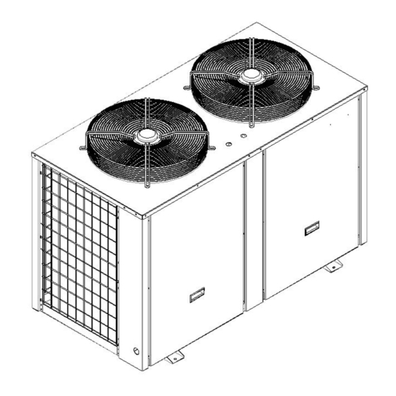
Section 1 Introduction Product Overview Swimming pool water chiller & heat pumps transfer heat from the ambient air to your swimming pool, providing the most energy efficient swimming pool and spa chilling and heating available. Compared to gas, oil, or electric heaters, operation cost of swimming pool water chiller &... -
Page 6: Installation
Section 2 Installation The following general information describes how to install the swimming pool water chiller & heat pump. Note: Before installing this product, read and follow all warning notices and instructions. Only a qualified service person should install the heat pump. Materials needed for Installation The following items are needed and are to be supplied by the installer for all heat pump installations:... - Page 7 Swimming Pool Water Chiller & Heat Pump Specification VM-0PC3200 VM-0PC3200 VM-0PC32000 VM-0PC32001 VM-0PC3200 VM-0PC3200 Model Advised pool volume (m 40~85 80~170 120~250 150~300 210~400 260~500 Operating air temperature (℃) -7~43 Performance Condition: Air 27°C, Water 26°C, Humidity 80% Heating capacity (kW) 26.0 51.5 75.0...
-
Page 8: Installation Location
Note: The above design and specifications are subject to change without prior notice for product improvement. Detailed specifications of the units please refer to name plate on the units. Correct installation is required to ensure safe operation. The requirements for heat pumps include the following: Dimensions for critical connections. - Page 9 The installation area must have good drainage and be built on a solid foundation. Do not install the unit in areas accumulated with pollution like aggressive gas (chlorine or acidic), dust, sand and leaves etc. For easier and better maintenance and troubleshooting, no obstacles around the unit should be closer than 500mm.
-
Page 10: Drainage And Condensation
The acceptable operating voltage range should be within ±10% of the rated voltage. When heat pump units are installed in parallel, ensure that the voltage differences, between these units, are within ±2%. 9. The heat pump unit must be grounded /earthed for safety purposes. Drainage and Condensation Condensation will occur from the evaporator when the unit is running and drain at a steady rate, depending upon ambient air temperature and humidity. -
Page 11: Plumbing Installation Requirements
The heat pump must be protected from back-siphoning of water. If there is any chance of back-siphoning, provide a check valve between the swimming pool and the heat pump outlet. Arrangement of pool system components are Chemical Feeders, Chemical Resistant Feeder Check Valve, Filter and Pool Pump. It is recommended to install the pressure switches, at both end of water Inlet and Outlet, which can be adjusted to accommodate this effect if the heat pump water connections are no more than six feet below the pool water surface or no more than fifteen 15 feet above... -
Page 12: Electrical Connections
Install a drain valve at the lowest point of the system to enable the system to be drained during freezing conditions (winterizing). Install a check valve on the water outlet connection in order to prevent back siphoning when water pump stops. In order to reduce the back pressure, the pipes should be installed horizontally 8. -
Page 13: General Information
General Information Wiring connections must be done according to the wiring diagram found on the inside of the heat pump access panel or see addendum A for reference. The heat pump must be grounded / earthed. A ground lug is provided on the inside of the heat pump electrical compartment. -
Page 14: Electrical Wiring Diagram
Electrical Wiring Diagram VM-0PC3200026 Page 14 of 21 This document is subject to change without prior notice. - Page 15 VM-0PC3200052/100/121/145 Page 15 of 21 This document is subject to change without prior notice.
-
Page 16: Operating Heat Pump
Section 3 Operating Heat Pump 1.Displays the interface 2.Wire control button definition On-OFF button In the unlocking state, long press this button for 1 second to switch on / off; In other settings, press this button to return to the main interface; ... - Page 17 Parameter query and settings User parameter query and setting (switch switch can be set) Under the main interface, long press "Function" button for 3 seconds to enter the user parameter query interface; press "+" button or "-" button to query each parameter;...
- Page 18 interface of the hour time of group 1, and the number of the hour part of the timing startup time flashes. Then press "+" or "-" to set the hours of group 1; When set the hour part of the timing boot, and then press the "timing" ...
-
Page 19: Parameters, Status, And Fault Code List
4.Parameters, status, and fault code list a.Unit parameter table User parameters (user operational setting) Set the code Parameter name justification range initial value Press start and set temperature return 2℃~18℃ 3℃ setting Set the temperature for heating 5℃ ~ Parameter F1 28℃... - Page 20 manually selected Automatic automatically Manual steps 2~50 electronic expansion valve Set the upper temperature 20℃~99℃ 40℃ upper limit of the water tank During electric heating, 0: Don't open, 1: Open circulating pump selects temperature deviation between the water -5℃~15℃ 0℃ tank temperature and the display temperature Installation and selection of...
- Page 21 Compressor 2 current (not available when selected for a single system) Expansion valve 2 opening (not available when single system is selected) b 10 Cooling coil # # 2 temperature -31℃~99℃ Fault Code History Fault Code History Fault Code History Fault Code History Fault Code History Fault Code History...
Need help?
Do you have a question about the VM-0PC3200026 and is the answer not in the manual?
Questions and answers