Advertisement
Quick Links
Advertisement

Summary of Contents for Anyload 563YHM4-02
- Page 1 563YHM4-02 Installation Manual | V24A 563YHM4-02 Installation Manual...
-
Page 2: Table Of Contents
563YHM4-02 Installation Manual | V24A ABLE OF ONTENTS Introduction ................................. 2 Weighing system configurations ......................5 Unpacking ................................6 Installation ................................7 Calibration ................................19 Troubleshooting ............................. 20... - Page 3 This manual provides how to assemble and install 563YHM4-02 weigh module in the application. This manual is intended to be used by trained service technicians and installers. It is recommended to go through the manual in details before installing, operating or configuring the instrument.
-
Page 4: Introduction
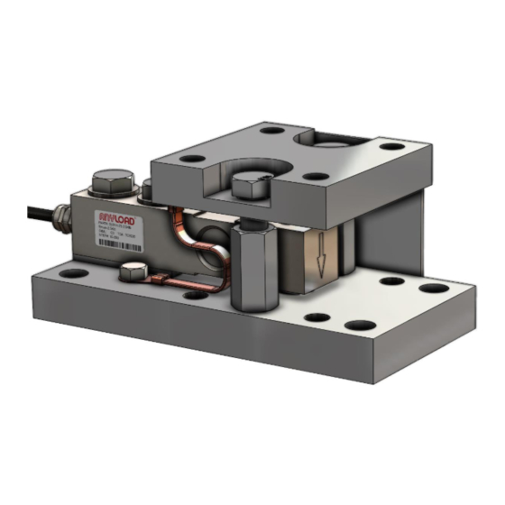
1. I NTRODUCTION The 563YHM4-02 weigh module is a versatile weigh module design with superior load introduction. It is constructed with superior Alloy Steel material and capacity range is from 100lb to 20klb. This design includes integral uplift protection and overload protection mechanism against catastrophic failure. - Page 5 563YHM4-02 Installation Manual | V24A Overload protection gap against catastrophic failure • checking & side load protection of 50% from the rated capacity The gap between the bolt and the through hole on the top plate allow and ensure checking and the side load protection up to 50% of the rated capacity (Largest capacity of the range).
- Page 6 563YHM4-02 Installation Manual | V24A Rocker pin • Versatile mounting options for conventional tank/vessel leg o Able to use existing 4-square tank leg mount holes in floor o Free to rotate for fixed position 360° w/same 4-mount holes o Able to flip entire mount 180° for further mount options Same mounting hole pattern as top plate •...
-
Page 7: Weighing System Configurations
563YHM4-02 Installation Manual | V24A 2. W EIGHING SYSTEM CONFIGURATIONS It’s determined by the number of existing support legs of the tank/silo. If a tank has four Number of weigh modules three, four, or more mounts. It should be avoided more than eight modules’ systems as even legs, then four weigh modules are needed. -
Page 8: Unpacking
• Load cells are shipped separately for a better protection during the shipping. • Anyload recommends to remove the load cells and weigh module from the packaging just before installation as they are more secure inside the packaging than outside. -
Page 9: Installation
563YHM4-02 Installation Manual | V24A • Although both load cells and the weigh modules are designed for harsh environments, the load cells are precision instrument and should be handled very carefully. UNDER NO CIRCUMSTANCES SHOULD THE LOAD CELLS EVER BE LIFTED BY THE CABLE. - Page 10 563YHM4-02 Installation Manual | V24A Installation on metal support with bolts Gaskets Metal support Anyload @ www.anyload.com...
- Page 11 563YHM4-02 Installation Manual | V24A Top plate mounting bolt Load cell mounting bolt torque to 22 ft-lb/30 Nm torque to 72 ft-lb/98 Nm Bottom plate mounting bolt All weigh modules must be in the same plane torque to 22 ft-lb/30 Nm within 3mm (1/8") and level within 0.5°...
- Page 12 (L) as long as the weight from the actual value. Anyload recommends to use flexible connection between the tank and the pipe as illustrated in the picture below. If the rigid connection cannot be possible to have a flexibility.
- Page 13 Load cell assembling to the weigh module 563YHM4-02 weigh modules and load cells are shipped separately and they may need to be assembled together before install to the tank weighing system depending on the installation method. Follow the steps below to assemble the load cell to the weigh module, DO NOT ADJUST LIFT-OFF PROTECTION BOLTS (#12) AND CHECK NUTS (#8) AT ANY TIME.
- Page 14 563YHM4-02 Installation Manual | V24A Loading screw 2. Remove the side plate (#10) from the weigh module. 3. Insert the rocker pin (#9) to the load cell from the top side (this is for 563YH-23 type load cell) Anyload @ www.anyload.com...
- Page 15 563YHM4-02 Installation Manual | V24A Rocker pin For the 563YH type load cell, use the extra ring as shown below, Middle ring 4. Install the loading cup to the top plate and insert the load cell + rocker pin at the same time such as the loading cup sit on the rocker pin.
- Page 16 563YHM4-02 Installation Manual | V24A 5. Place the spacer (#4) underneath of the load cell and two washers on top of the load cells as shown below and tighten the load cell bolts with 72ft-lb/98Nm. 6. Fix the shipping/alignment stopper back.
- Page 17 563YHM4-02 Installation Manual | V24A load cells have already been installed in the weigh modules and they can be damaged due to the shock loads with sudden lowering the tank. Installation method 2 In this method the load cell is not assembled to the weigh module when the tank is assembled to the weighing system.
- Page 18 563YHM4-02 Installation Manual | V24A Top surface of the bolt Top surface of the top plate Lower the tank on to the weigh modules and weld/fix the bolts. Anyload @ www.anyload.com...
- Page 19 563YHM4-02 Installation Manual | V24A Remove the alignment plates after proper alignment and installation of the tank. Anyload @ www.anyload.com...
- Page 20 563YHM4-02 Installation Manual | V24A Lift the top plates/tank and install the load cells. DO NOT REMOVE/ADJUST TWO LIFT-OFF BOLTS AT ANY TIME DURING THIS INSTALLATION PROCESS. Electrical installation depending on the application requirement. It’s not recommended to cut or attach cable to match 563YH/563YH-23 load cells are available with different cable length options as 6m or 10m Load cell cable must be protected by conduit if it’s installed in a...
-
Page 21: Calibration
Because of the design or size of the weighing system it may not be feasible to use test weights equal to the full-scale capacity of the system and Anyload recommends using any other alternative method as listed below in such situations. -
Page 22: Troubleshooting
563YHM4-02 Installation Manual | V24A 8. T ROUBLESHOOTING Electrical trouble shooting 2. Check the ADC count on the instrument (indicator) and check whether it’s sensitive to 1. Check the power to the instrument. the weighing system. 3. If The ADC count is not sensitive to the weighing system, then, check the excitation voltage at the instrument, junction box and load cells. - Page 23 It is important to identify any mechanical problem such as leveling issues, vibrations, shifting, etc to get accurate measurement from the weighing system. Anyload recommends checking the whole mechanical structure thoroughly to identify such issues if there are some errors such as non-repeatability, instability, non-linearity or zero shift, etc on the weighing indicator reading.
- Page 24 563YHM4-02 Installation Manual | V24A Please Contact our Authorized Dealer for Technical Assistance: North America Toll Free: 1.855.ANYLOAD (269.5623) Email: info@anyload.com www.anyload.com Anyload @ www.anyload.com...
Need help?
Do you have a question about the 563YHM4-02 and is the answer not in the manual?
Questions and answers