Table of Contents
Advertisement
Quick Links
Advertisement
Table of Contents

Summary of Contents for Metal Man 220iDV
- Page 1 Inver ter Powered Multi-Process 220iDV OWNER’S MANUAL 07/2018 WARNING: Read carefully and understand all ASSEMBLY AND OPERATION INSTRUCTIONS before operating. Failure to follow the safety rules and other basic safety precautions may result in serious personal injury.
-
Page 2: Limited Warranty
Limited to the warranty periods below, Metal Man Work Gear Co will repair or replace the item under warranty that fails due to defects in material and workmanship. Metal Man Work Gear must be notified within 30 days of the failure, so as to provide instructions on how to proceed with the repair of your welder and warranty claim processing. -
Page 3: General Safety Rules
GENERAL SAFETY RULES WARNING: Read and understand all instructions. Failure to follow all instructions listed below may result in serious injury. CAUTION: Do not allow persons to operate or assemble this Flux Core 125 until they have read this manual and have developed a thorough understanding of how the Flux Core 125 works. - Page 4 -Do not allow any body part to come in contact with the welding wire if you are in contact with the material being welded, ground or electrode from another welder. -Do not weld if you are in an awkward position. Always have a secure stance while welding to prevent accidents.
- Page 5 -Always use a helmet that covers your full face from the neck to top of head and to the back of each ear. -Use a lens that meets ANSI standards and safety glasses. For welders under 160 Amps output, use a shade 10 lens;...
- Page 6 Electromagnetic Field -Electromagnetic fields can interfere with various electrical and electronic devices such as pacemakers. -Consult your doctor before using any electric arc welder or cutting device -Keep people with pacemakers away from your welding area when welding. -Do not wrap cable around your body while welding. -Wrap MIG gun and ground cable together whenever possible.
-
Page 7: Technical Specifications
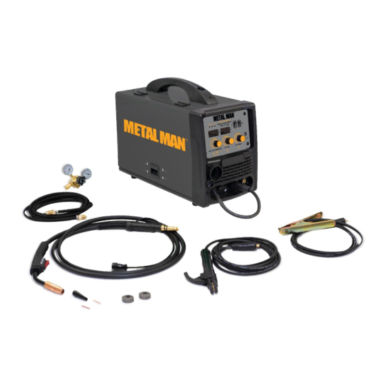
ACTT1, the optional TIG Torch. This Metal Man Inverter Powered Multi-Process 220iDV is capable of MIG welding 5/16ʺ steel in a single pass while using 220V input power (3/16” steel when using 120V input power). It uses leading edge Inverter Technology to provide high quality welds that are crisp, clean, and consistent with plenty of power that will impress the most experienced of welders. -
Page 8: Power Indicator Light
Spool Gun/ Spot Timer Digital Indicator MIG Torch/Stick On/Off Meters Lights Welding Selector Wire Speed & Amperage Control Spot Time Regulator/ Adjustment Flowgauge Hose Voltage Setting Ground Cable And Clamp Electrode Holder And MIG Torch Cable POWER INDICATOR LIGHT In the “OFF” position no power is being supplied to the torch. In the “ON” position power is supplied to the main transformer and control circuit. - Page 9 SPOOL GUN/MIG TORCH/STICK WELDING SELECTOR When normal MIG welding, this switch should be turned in “MIG” position. When using the spool gun, the switch should be in “spool gun” position. When DC stick welding, the switch will be in the "stick" position. SPOT TIME ADJUSTMENT The Spot Time Adjustment allows you to set a time from 0.1 to 9.9 seconds for consistent spot welds.
- Page 10 1.3 Insert the back end of the MIG torch into the MIG socket on the front of your machine. Make certain to completely slide the torch all the way in. Slightly twist to assist with pushing the torch to the back of the receptacle.
- Page 11 2.3 We recommend removing the MIG torch when the Spool Gun is connected to avoid accidental arcing. Loosen the wing nut retaining bolt and slide the MIG torch out of the front of the machine. Disconnect the 5-Pin trigger connection on the front of the machine. 2.4 Carefully slide the gas connector (1) and the weld power connection (2) through the weld cable access opening in the front of the machine.
- Page 12 2.9 Make certain the SPOOL GUN/MIG TORCH/STICK SELECTOR on the front panel is switched into the SPOOL GUN position. 3. DC STICK WELDING ASSEMBLY Be aware that the ELECTRODE HOLDER will be electrically HOT when the Input Power Switch on the welder is turned on.
-
Page 13: Installation
4. OPTIONAL TIG TORCH ASSEMBLY Be aware that the TIG torch will be electrically HOT when the Input Power Switch on the welder is turned on. 4.1 Remove the ground cable and the electrode holder from the weld output connections. Install the ground cable to the Positive (+) weld output connection. - Page 14 4. INSTALL THE WIRE ROLLER - The wire roller has been factory installed. However, check to make certain the correct wire groove is in place to accommodate the size of wire you are using. Open the wire feed compartment. Adjust the drive roller according to the following steps; see following picture about the wire feeder structure: a.
- Page 15 on this unit. Select welding wire - Both four-inch or eight-inch wire spools of 0.023 or 0.030 wire can be used on this welder. NOTE: - Burn through can occur if you attempt to weld mild or stainless steel thinner than 24 gauge. - Remove all rusted wire from your wire spool.
- Page 16 The welder can use either 4-inch or 8-inch spools. See the following figure for additional reference. The wing nut controls the tension on the spool. 8-Inch 4-Inch Setting the wire spool tension. a) Turn the spool of wire with one hand. b) Increase the spool tension by tightening (turn clockwise) the wing nut while turning the spool.
- Page 17 -Make certain that the welding wire is actually going into the torch liner. If not, the wire will jam up in the mechanism. m. Line the wire up with the correct groove in the drive roller. Place the drive tension arm back above the drive roller.
-
Page 18: Gas Installation
7. GAS INSTALLATION Shielding gas cylinders and high pressure cylinders can explode if damaged, so treat them carefully. • Never expose cylinders to high heat, sparks, open flames, mechanical shocks or arcs. • Do not weld on the cylinder. • Always secure cylinder upright to a cart or stationary object. - Page 19 g. Open the Gas Bottle Valve on the cylinder of gas. h. Turn the Gas Flow Adjuster on the regulator so that the gas flow rate is set at approximately 20 CFM. Make certain you are reading the correct scale on the gauge. NOTE: Slowly open the cylinder valve by turning it counterclockwise until the cylinder pressure gauge registers on the first gauge of the regulator.
- Page 20 MIG OPERATION Electrical Shock • High voltage danger from power source! Consult a qualified electrician for proper installation of receptacle. This welder must be grounded while in use to protect the operator from electrical shock. • Do not remove grounding prong or alter the plug in any way. Use only the supplied adapter between the welder's power cord and the power source receptacle.
-
Page 21: Welding Techniques
6. DISTANCE FROM THE WORK PIECE - If the nozzle is held off the work piece, the distance between the nozzle and the work piece should be kept constant and should not exceed 1/4 inch or the arc may begin sputtering, signaling a loss in welding performance. 7. - Page 22 ELECTRIC SHOCK CAN CAUSE INJURY OR DEATH! To prevent ELECTRIC SHOCK, do not perform any welding while standing, kneeling, or lying directly on the grounded work piece. 8.1 Moving the torch Torch travel refers to the movement of the torch along the weld joint and is broken into two elements: Direction and Speed.
- Page 23 8.3 Welding position FLAT POSITION is easiest of the welding positions and is most commonly used. It is best if you can weld in the flat position if at all possible as good results are easier to achieve. HORIZONTAL POSITION is performed very similarly to the flat weld except that angle B (see HOLDING THE TORCH) is such that the wire, directed more toward the metal above the weld joint is to help prevent the weld puddle from running downward while still allowing slow enough travel speed.
- Page 24 falling into the nozzle. Angle B should be held at zero degrees so that the wire is aiming directly into the weld joint. If you experience excessive dripping of the weld puddle, select a lower heat setting. Also, the weave bead tends to work better than the stringer. 8.4 Multiple pass welding Butt Weld Joints: When butt welding thicker materials, you will need to prepare the edges of the material to be joined by grinding a bevel on the edge of one or both pieces of the metal being joined.
- Page 25 8.5 Spot welding There are three methods of spot welding: Burn-Through, Punch and Fill, and Lap. Each has advantages and disadvantages depending on the specific application as well as personal preference. 1. The BURN-THROUGH METHOD welds two overlapped pieces of metal together by burning through the top piece and into the bottom piece.
-
Page 26: Setting Up The Work Piece
1. Select the wire diameter and heat setting recommended above for the method of spot welding you intend to use. 2. Tune in the wire speed as if you were going to make a continuous weld. 3. Hold the nozzle piece completely perpendicular to and about 1/4 inch off the work piece. 4. - Page 27 2. GROUND CLAMP CONNECTION Clear any dirt, rust, scale, oil or paint on the ground clamp. Make certain you have a good solid ground connection. A poor connection at the ground clamp will waste power and heat. Make sure the ground clamp touches the metal. 3.
- Page 28 4.1. When proper rod is used: 4.1.a. The bead will lay smoothly over the work without ragged edges 4.1.b. The base metal puddle will be as deep as the bead that rises above it 4.1.c. The welding operation will make a crackling sound similar to the sound of eggs frying 4.2.
- Page 29 work piece should be between 10 and 30 degrees. This will allow for good penetration, with minimal spatter. 6.2 Striking the arc EXPOSURE TO A WELDING ARC IS EXTREMELY HARMFUL TO THE EYES AND SKIN! Prolonged exposure to the welding arc can cause blindness and burns. Never strike an arc or begin welding until you are adequately protected.
- Page 30 The weave bead: Used when you want to deposit metal over a wider space than would be possible with a stringer bead. It is made by weaving from side to side while moving with the electrode. It is best to hesitate momentarily at each side before weaving back the other way. 6.4 Welding position Flat position: It is easiest of the welding positions and is most commonly used.
- Page 31 accumulation of dirty metal scale on the finished weld. Slag should be removed by using a chipping hammer. PEENING THE SLAG FROM A WELD JOINT CAUSES SMALL CHIPS OF METAL TO FLY THROUGH THE AIR! Metallic chips flying through the air can cause eye injury or injury to other parts of the head, hands or exposed portions of the body.
-
Page 32: Maintenance
8. Follow these steps for striking an arc while TIG welding. a. Open the shielding gas valve on the torch handle to begin gas flow. b. Rest the TIG torch nozzle on the work piece making sure to not touch the installed tungsten electrode. -
Page 33: Troubleshooting
TROUBLESHOOTING SYMPTOM POSSIBLE CAUSE CORRECTIVE ACTION Unit does not power up Unit is not plugged in Plug in unit Input power circuit breaker not on Reset input power circuit breaker The main power switch is not working Replace main power switch Protection indicator is on The internal temperature is too high. - Page 34 MAIN CIRCUIT CHART...
-
Page 35: Diagram & Parts List
DIAGRAM & PARTS LIST... - Page 36 STOP TIMER ON/OFF SWITCH 145200023 POTENTIOMETER KNOB YELLOW 105800030 PROCESS SELECTOR SWITCH 105800031 FRONT PANEL PC BOARD SUPPORT 145200031 FRONT PANEL DECAL MULTI-PROCESS 220iDV 105800032 FRONT PANEL PC BOARD 105800033 WIRE FEEDER SUPPORT PLATE 105800034 WIRE FEEDER SUPPORT PLATE 2 105200055...
- Page 37 Metal Man Work Gear Company 1760 Prospect Ct #120 Appleton, WI 54914 w w w . m e t a l m a n g e a r . c o m 8 8 8 - 7 6 2 - 4 0 4 5...
Need help?
Do you have a question about the 220iDV and is the answer not in the manual?
Questions and answers